7.3 Performance Test for Sampling Oscilloscope
7-27
7
Performance Test
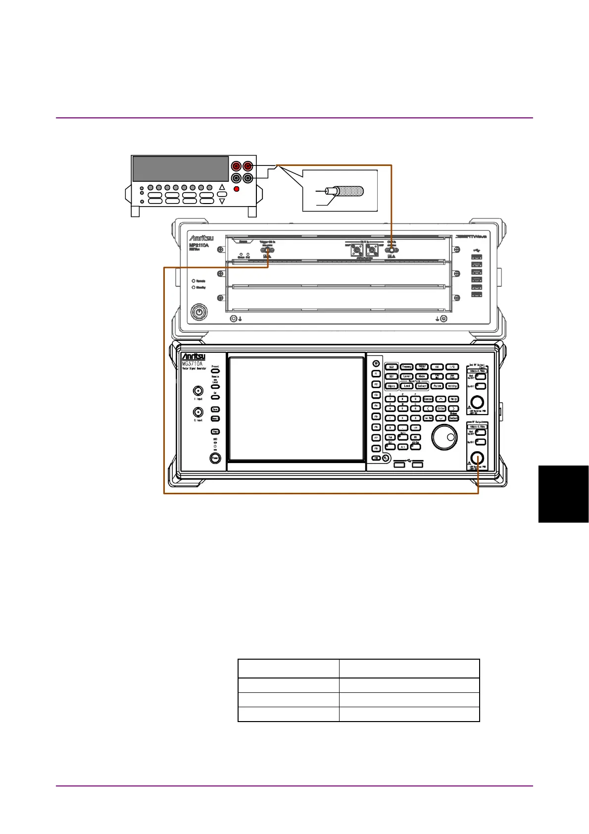
Figure 7.3.2-3 Amplitude Accuracy Test Connection Diagram
(When using a signal generator)
(3) Procedure
1. In case of Figure 7.3.2-2, connect the
Sync Out
connector and
the
Trigger Clk In
connector using a coaxial cable.
In case of Figure 7.3.2-3, connect the
Trigger Clk In
connector
and the signal generator
output
connector using a coaxial cable.
2. In case of Figure 7.3.2-2, click PPG/ED Ch1. Configure the
settings as shown below:
Item Setting Value
Reference Clock Internal
Bit Rate Variable, 28 Gbit/s, 0 ppm
Sync Output PPG_1/8 Clk
In case of Figure 7.3.2-3, set the signal generator as follows:
Frequency: 3.5 GHz
Amplitude: 0.5 Vp-p (at sine-wave –2.0 dBm)
Coaxial Cable
+
-
DC Power Supply