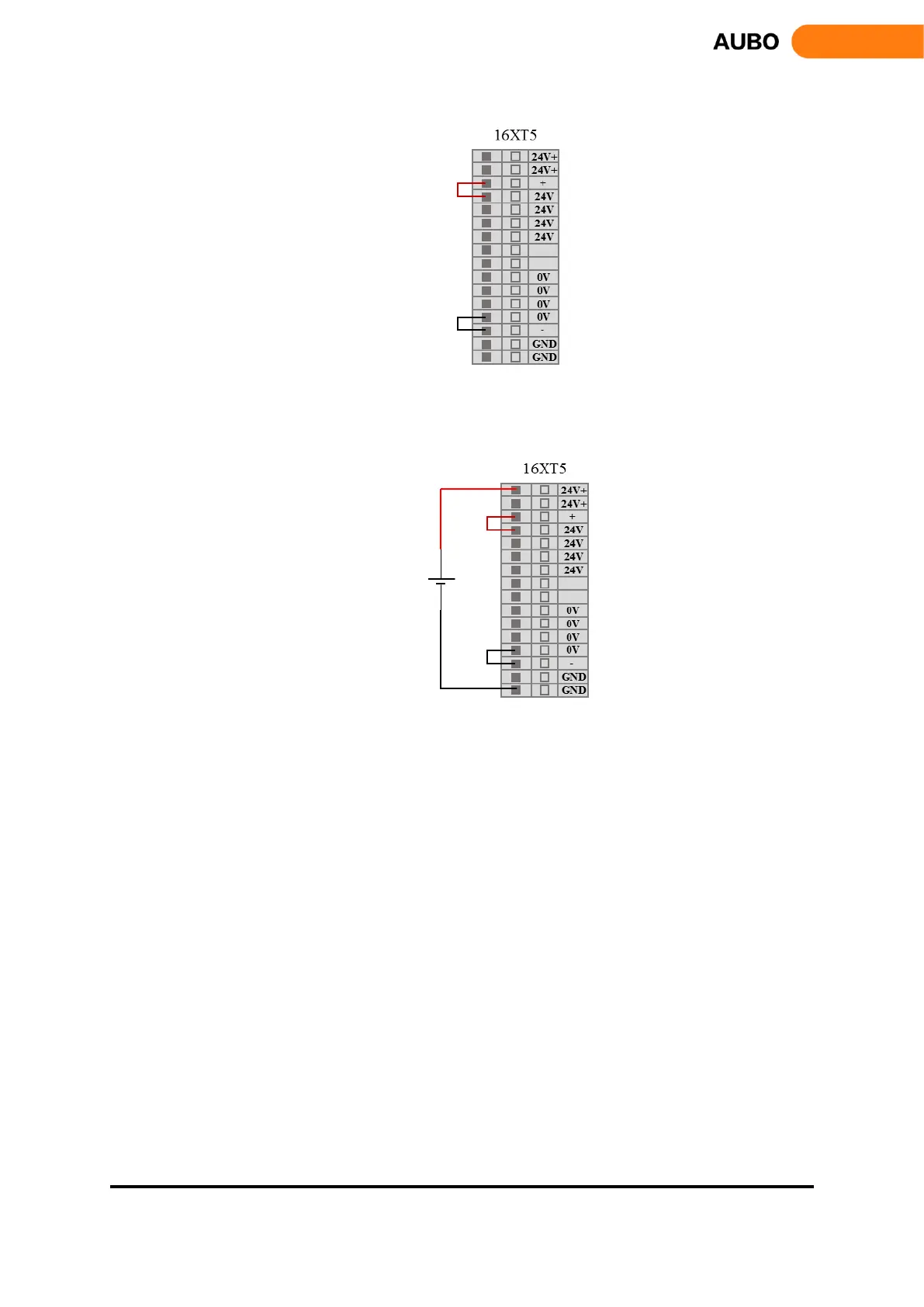
Figure 8.21 Internal power supply
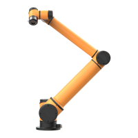
External power supply:
Figure 8.22 External power supply
1、 Digital input
Interface board has 16 digital inputs (Hereinafter use "DI" to represent digital input). They work as NPN,
which means inputting low voltage to DI trigger action. Inputting high voltage to DI does not trigger action.
DI terminal can read the switch button, sensors, PLC or other AUBO robot operation signals. Some common
wirings will be listed in following examples.
Some common wirings will be listed in following examples.
1) DI connect to button switch
As shown in figure 8.11, DI through a normally open button connected to the ground (G). When the button
is pressed, DI and GND are connected, which is equivalent to inputting low voltage to DI and triggering
action. When the button is not pressed, DI and GND are disconnected and won’t cause any action. This is
the easiest wiring example.