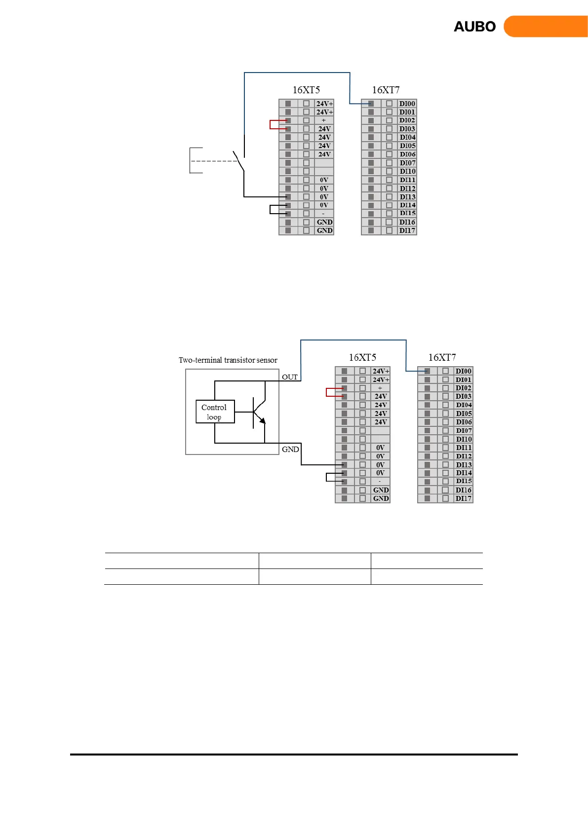
Figure 8.23 DI connect to button switch
2) DI connects to two-terminal sensor
As shown in figure 8.12, the DI and GND are connected to a sensor. If the voltage difference between
OUT and GND are very small when sensor is working, it can trigger action too. When the sensor does not
work, and the circuit is disconnected, it does not cause any action.
Figure 8.24 DI connect to two-terminal sensor
Electrical parameters of DI are as follows:
a) Digital output
Interface board has 16 digital outputs (Hereinafter use "DO" to represent digital output). They work as
NPN as shown in figure 8.13. When given a logical "1", DO is connected to GND and output is low. When
given a logic "0", DO is connected to GND, and output is high.
DO terminals can be connected directly to the load to communicate with PLC or another robot.