SECTION 58 - ATTACHMENTS / HEADERS - CHAPTER 1
58-3
Each disc module is a separate gear case with its
own oil sump, and utilizes precision forged gears for
strength. Each module consists of a top cap
assembly and a lower module assembly.
The top cap assembly consists of the top cap
housing, a bevel gear shaft, a matched bearing set
and a disc hub. The top cap assembly can be
removed from the module for servicing, without
disassembling the cutter bar.
The lower module assembly consists of the lower
module housing and the pinion shaft and bearing
assembly. Because the pinion shaft runs at 5400
RPM, steel slingers are mounted at each end to
splash oil on the shaft seals for lubrication and
cooling.
The direction of rotation of the disc module is
determined by the installation of the pinion shaft; if
the pinion shaft is installed with the gear positioned
on the right side of the housing, the disc will rotate
clockwise. Installing the pinion shaft with the gear to
the left will rotate the disc counterclockwise.
CBAR
3
If a problem is found with a specific module, the
extent of the damage can be quickly determined by
removing the disc and the top cap assembly of the
affected module. If damage is limited to the top cap
assembly components, the lower module can be
flushed out to remove contaminants, and a new top
cap assembly installed to complete the repair.
50012156
4
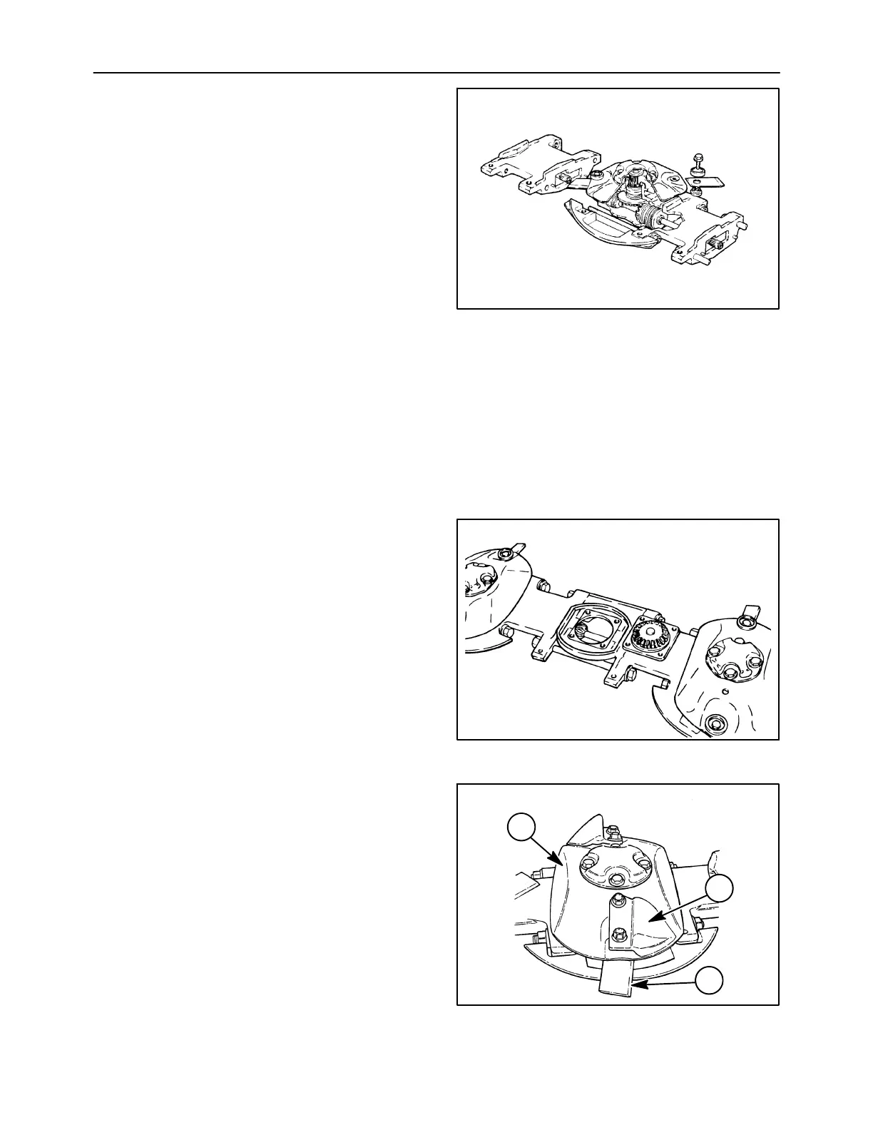
The cutter bar uses small diameter, high-profile
discs, 1, which are 3/16 inch thick and hardened for
long wear. The profile of the discs,combined with bolt
on lifters, 2, provide aggressive feeding to the
conditioner rolls in difficult crop conditions.
The discs, 1, are equipped with 2-inch wide knives,
3, which are retained with 1/2″ bolts and hardened
knife nuts. The knives are reversible for long life, and
always have the beveled edge up. An arrow is
stamped on both sides of the knife to show the
direction of rotation.
1431-2-48
1
2
3
5