SECTION 58 - ATTACHMENTS / HEADERS - CHAPTER 1
58-29
The backlash of the assembled disc module is
controlled by precision machining of the disc module
and top cap housings, the use of precision forged
gears, and the use of low tolerance bearings, which
are manufactured to provide a specific “stack height,”
or combined thickness. The backlash in the gear set
should be 0.13 -- 0.28 mm ( 0.005 -- 0.011 in) after the
module has been assembled.
If the back lash is found to be incorrect after gearbox
repair with new parts, recheck the module for correct
assembly of all components.
NOTE: Each bearing for the pinion shaft is
manufactured for a specific “stack height”. Do not mix
old and new bearing components or substitute with
“jobber” bearings.
1. Install a snap ring, 1, on the pinion side of module
casting. Slide the bearing cup for the pinion side
bearing into the housing bore against snap ring.
Note that the direction of rotation desired will
affect which side of housing you start on. For
example, install snap ring on right side of housing
for clockwise rotation, and on the left side of
housing for counter-clockwise rotation.
A3654-11
1
66
2. Support the module housing approximately 1/2
inch above the work surface on blocks, a large
piece of pipe as shown, or in an open vise;
position the snap ring and bearing cup down, 1.
Slide the assembled lower module shaft into
housing, making sure pinion side is down against
snap ring to orient properly for desired direction
of rotation.
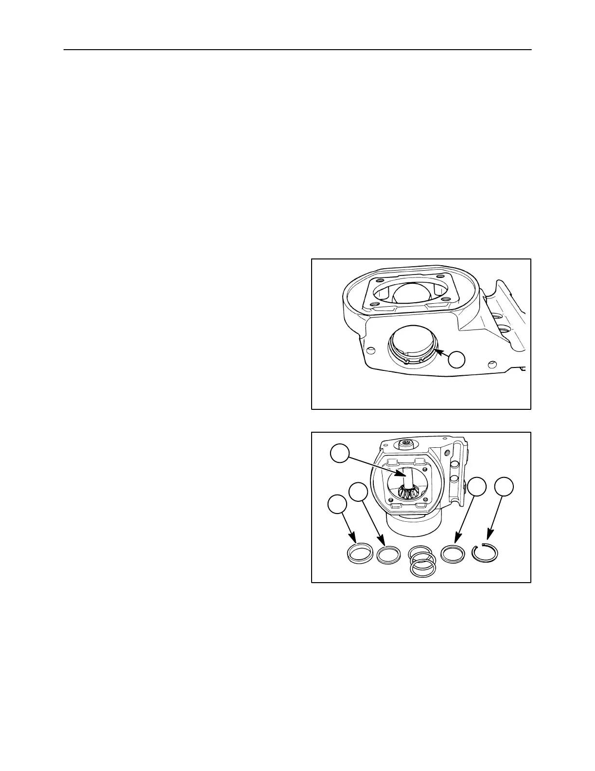
3. Install the bearing cup, 2, that goes with the
upper bearing cone into the housing. Place the
two spacer washers, 3, on top of the bearing cup,
and install the snap ring, 4, into the groove in the
housing.
A3654-10
1
2
3
3 4
67