SECTION 58 - ATTACHMENTS / HEADERS - CHAPTER 1
58-30
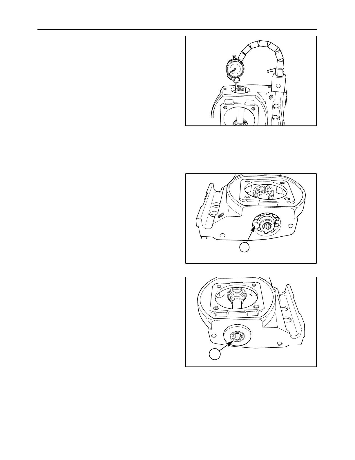
4. Check the end play of the pinion shaft with the
pinion side facing down, to ensure an accurate
measurement. Rotate the shaft two complete
revolutions to seat all components (bearing
rollers in cage), and install a dial indicator to
measure shaft end play. Allowable end play is
0.05 -- 0.20 mm (0.002 -- 0.008 in). Use a
screwdriver to pry upwards on the pinion gear to
obtain an end play reading. Remove the snap
ring and add the required thickness of shims
between the spacer washers to achieve the
correct end play.
NOTE: The shims must be sandwiched between two
hardened washers to protect them from the bearing
and the snap ring groove.
Recheck the end play as described above to
ensure the assembled end play is correct.
A3654-16
68
5. Install an oil slinger, 1, into the groove on each
end of the pinion shaft. Be careful not to scratch
the sealing surface on the shaft as this will cause
the shaft seal to leak, causing module failure.
The slingers are bidirectional in nature, and may
be installed in either direction on the shaft.
IMPORTANT: Usecautiontopreventthetipsofthe
slingers from contacting the sealing surface on the
end of the shaft, or seal failure will occur.
A3654-13
1
69
6. Apply grease to the sealing lip on the shaft seal,
1, and press them into place on each side of the
housing.
NOTE: The seal must be pressed into place with a
seal installing tool or suitable substitute. The seals
must be flush with the side of the housing, and square
to the shaft. If the seal is driven in with a hammer, it
will be distorted and leak, causing disc module
failure.
A3655-2
1
70