SECTION 58 - ATTACHMENTS / HEADERS - CHAPTER 1
58-32
CUTTER BAR DRIVE SHAFT -
DISASSEMBLY
1. Remove the four cap screws retaining the cutter
bar drive shaft, tower and disc to the disc hub at
1. Lift the tower and drive shaft slightly to clear
the disc hub bolt, and pull them forward so the
upper end of the drive shaft slides off the splined
shaft.
20011832
1
73
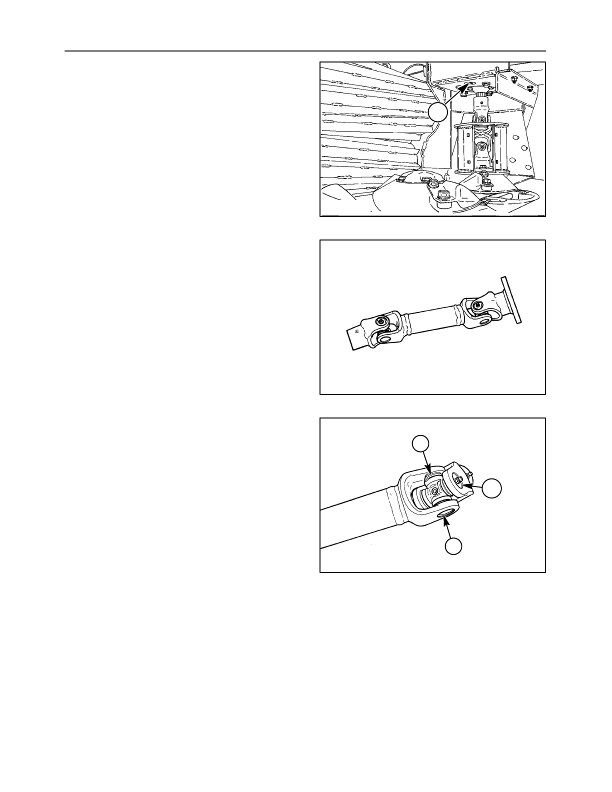
2. The drive shaft contains two U-joints, which may
be serviced individually.
1431-6-6
74
3. The U-joint bearing cups are retained with
external-type snap rings, 1, positioned on the
inner side of the yoke ears. Remove the snap
rings by positioning a screwdriver against the
open end of the snap ring, and give a light blow
to the screwdriver to pop the snap ring off the
bearing cup.
Remove the grease zerk, 2, from the one bearing
cup.
NOTE: The grease zerk is oriented to line up with
other grease zerks on the drive shaft. Note the
positioning of the grease zerk prior to removal.
1431-6-7
1
1
2
75