SECTION 58 - ATTACHMENTS / HEADERS - CHAPTER 1
58-33
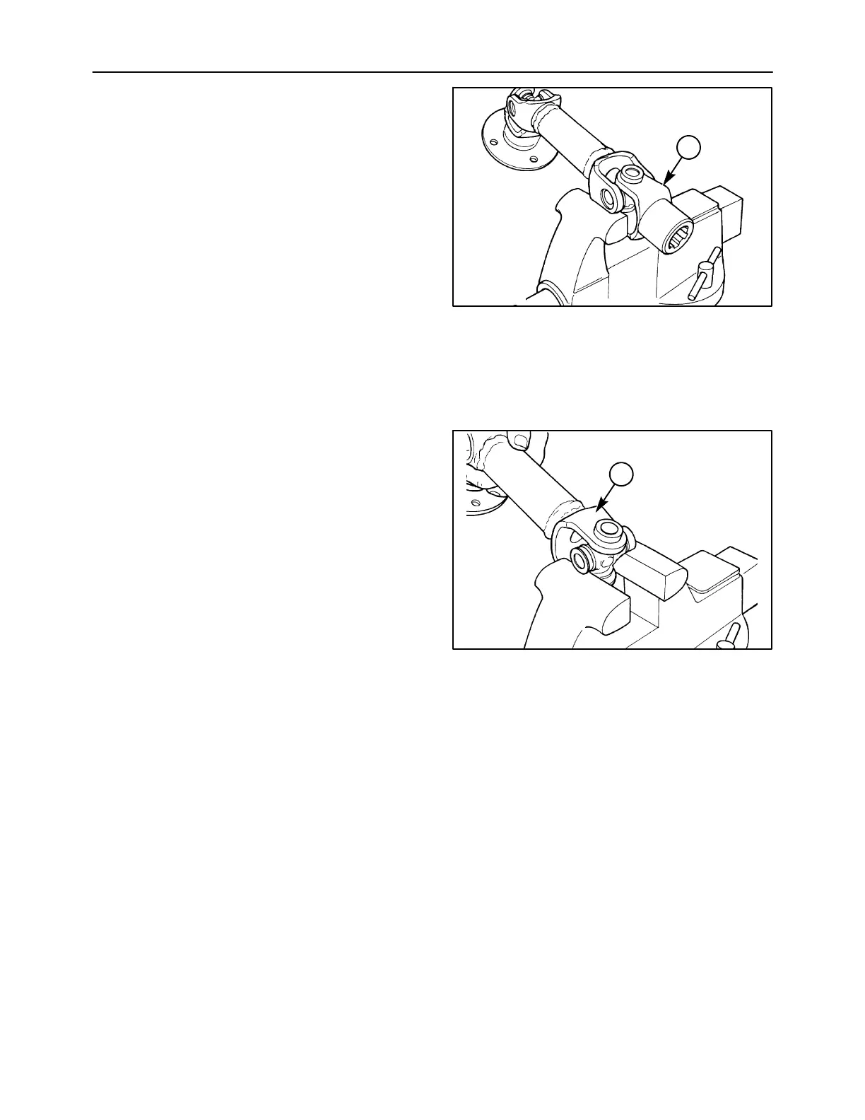
4. Position the joint in an open vise, with each ear
of one yoke supported by a vise jaw. With a soft
hammer of mallet, strike the top ear of the
unsupported yoke at 1. This will drive the top
bearing outward approximately 8 mm (1/4 in).
IMPORTANT: Do not use a hard faced hammer, as
this may damage the edge of the bearing cup bore in
the yoke, causing the bearing cup to hang up or seize
in the yoke.
5. Pull the bearing out of the yoke ear. If necessary,
grip the loosened bearing in a vise, and drive the
yoke off the bearing by striking the yoke ear with
the soft faced hammer or mallet.
6. This same procedure should be followed to
remove the bearing directly opposite the one just
removed, after which the yoke itself may be
removed.
1431-6-8
1
76
7. To remove the remaining two bearings, support
the cross in the vise, making certain the vise jaws
are covered with brass protectors or the
previously removed bearings are reinstalled on
the cross. By striking the yoke ear, 1, the
bearings can be removed as per steps 4 and 5.
1431-6-9
1
77