SECTION 58 - ATTACHMENTS / HEADERS - CHAPTER 1
58-34
CUTTER BAR DRIVE SHAFT - ASSEMBLY
1. To reassemble the U-joint, position the cross, 1,
in the yoke so that the bearing journals are
positioned in each yoke ear. Insert the bearings
in the outside of the yoke ears, and position the
assembly in a vise. Press the bearings in until
they are flush with the edge of the yoke.
2. Using a socket of the same diameter as the
bearing, press the bearing into the yoke ear until
the snap ring groove is exposed on the inside of
the yoke ear. Install the snap ring over the
bearing cup.
3. Reposition the yoke and cross in the vise, and
use the socket to press the opposite bearing fully
into the yoke ear while rotating the cross to
ensure it does not bind up. Continue to press the
bearing into the yoke ear until the snap ring can
be installed. It may be necessary to push the
bearing in as far as possible with the vise, and
then remove the yoke assembly and strike the
yoke ears with a sharp blow from a hammer to
spring the yoke enough to install the snap ring.
1431-6-10
1
78
4. Assemble the second yoke to the cross repeating
steps1to3.
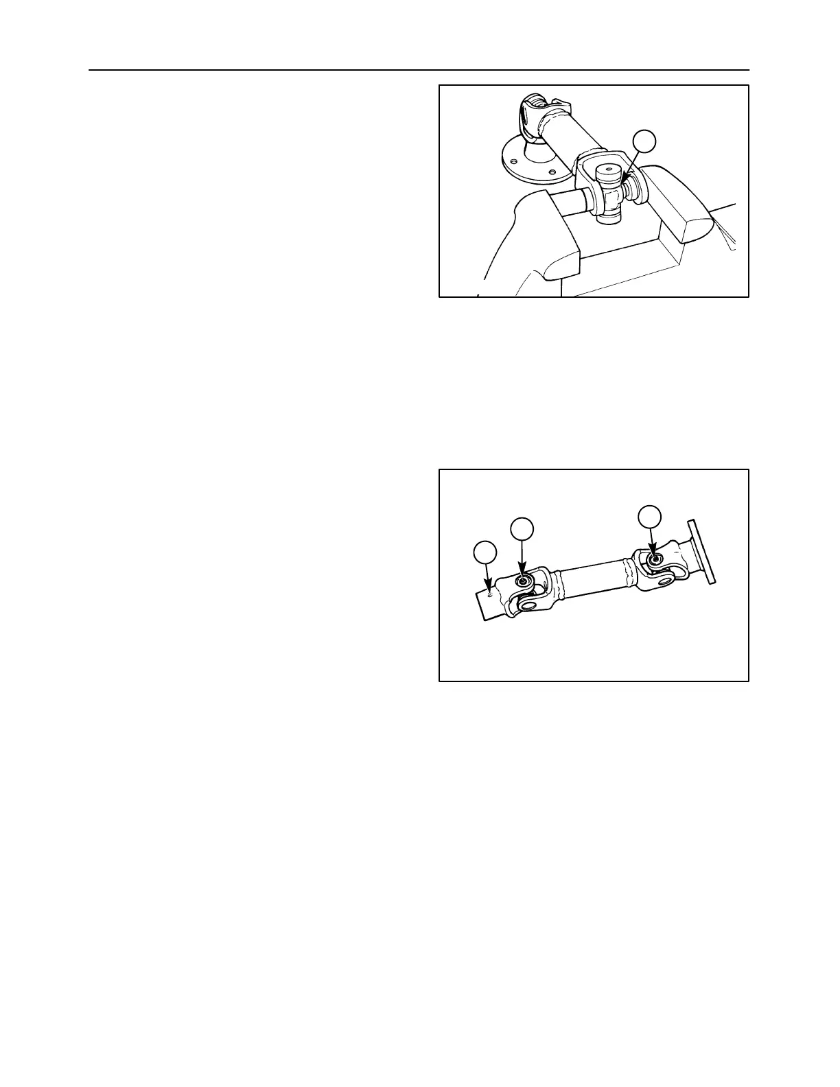
NOTE: The grease zerk, 1, should be oriented to line
up with the other grease zerks, 2, on the drive shaft
for ease of lubrication. Note the positioning of the
bearing cup for the grease zerk during reassembly to
ensure it aligns with the other grease zerks.
5. After complete assembly of the U-joint, strike the
forged surfaces of all yoke ears with a sharp blow
from a hammer. This will ensure proper seating
of the bearings, and eliminate any possible
tightness to ensure a free flexing joint.
IMPORTANT: Use caution not to strike the bearing
bore area of the yoke, as this will damage the bore
and may cause premature cross bearing failure.
1431-6-6
2
1
2
79