SECTION 58 - ATTACHMENTS / HEADERS - CHAPTER 2
58-9
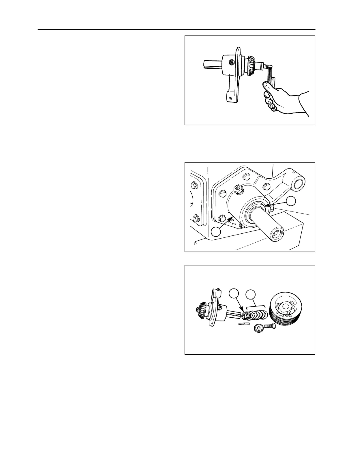
4. Install the flat washer and castellated nut onto the
shaft, and tighten the castellated nut as required
to obtain 0.23 -- 0.68 N⋅m (2 -- 6 in-lb) rolling
torque on the conditioner drive shaft assembly.
After adjusting the rolling torque, tighten or
loosen the nut as required in order to align it with
the hole in the shaft. If the nut must be rotated
more than one quarter of a flat to align it with the
hole, loosen off the nut, strike the shaft with a
soft-faced hammer to unseat the bearing cone,
and repeat the process. Recheck the rolling
torque prior to installing the cotter pin to ensure
it is correct.
IMPORTANT: Do not exceed 0.68 N
⋅
m(6in-lb)
rolling torque on the conditioner drive shaft
assembly, or bearing failure could occur.
1411/6-8
17
5. Lubricate the shaft seal lips liberally with grease,
and install the seal over the shaft and onto the
shoulder. Seat the seal, 1, into the housing, 2,
until it is flush with the outer face of the housing.
NOTE: The seal lip will engage on the shaft shoulder
at the same time the seal cage must be installed in
the housing bore; use caution to ensure the seal lip
does not roll outwards.
NOTE: Figure shows conditioner drive shaft
assembly installed on gearbox. Do not install
assembly until after input shaft rolling torque is
adjusted.
1411/6-16
1
2
18
6. Install the spacer, 1, with the bevel facing in
towards the shoulder on the shaft. Slide on the
washers, 2, install the key in the keyway so that
the end is flush with the end of the shaft, slide on
the sheave, and install the cap screw and flat
washer.
NOTE: It will be easier to torque the sheave retaining
bolt after installing the bevel gearbox back onto the
unit.
1411/6-2
2
1
19