SECTION 58 - ATTACHMENTS / HEADERS - CHAPTER 3
58-23
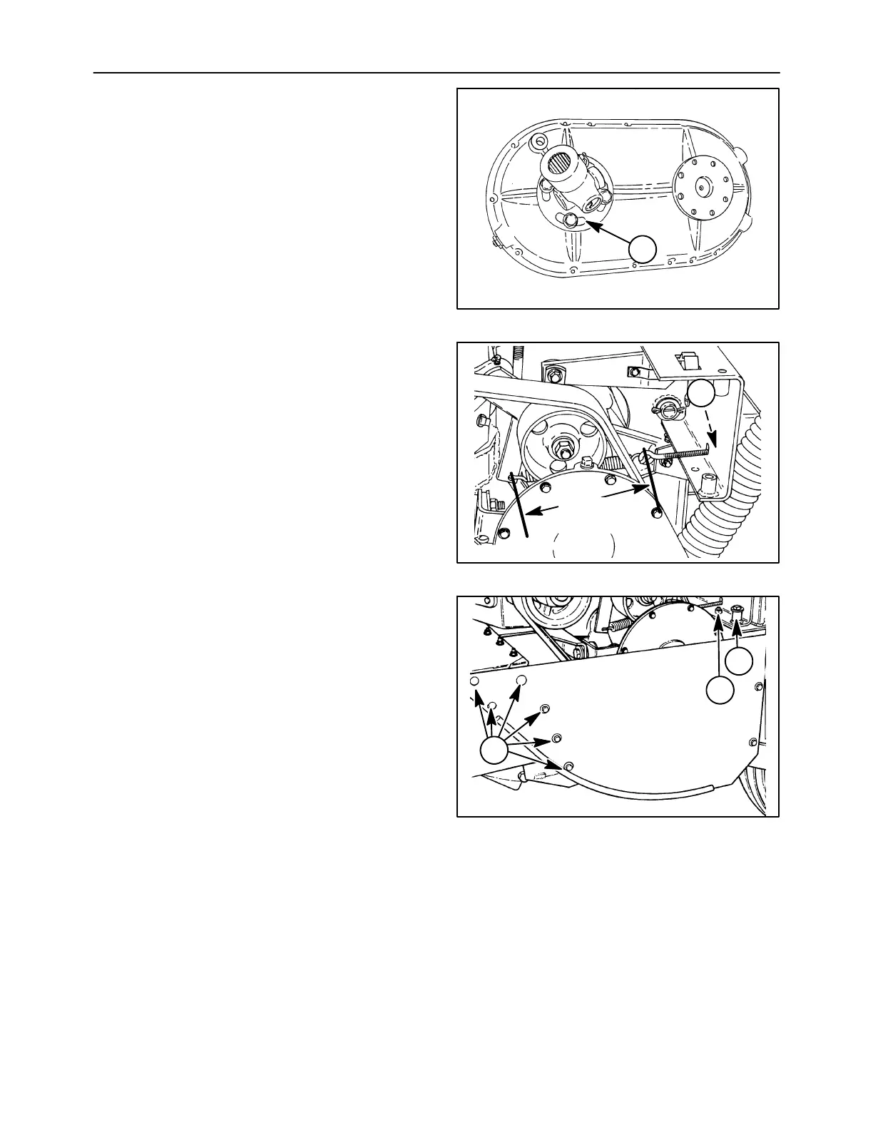
NOTE: The figure at right shows the slotted yoke
flange, 1, on the upper gearbox shaft removed from
the machine.
19992645
1
59
14. Position the conditioner drive belt on the sheaves
and tighten the nuts, 1, on the spring tension rod
to tension spring to a length of 279 mm (11 in)
between the hooks.
A3994-09
279 mm
(11 in)
1
60
15. Reinstall the divider sheet assembly using a cap
screw and locknut, 1, and six carriage bolts, lock
washers, and nuts, 2. If the left swing out shield
was removed, reinstall it on the unit using two cap
screws and locknuts at 3.
A3659-25
1
2
3
61