SECTION 31 - IMPLEMENT POWER TAKE-OFF (PTO) - CHAPTER 2
31-6
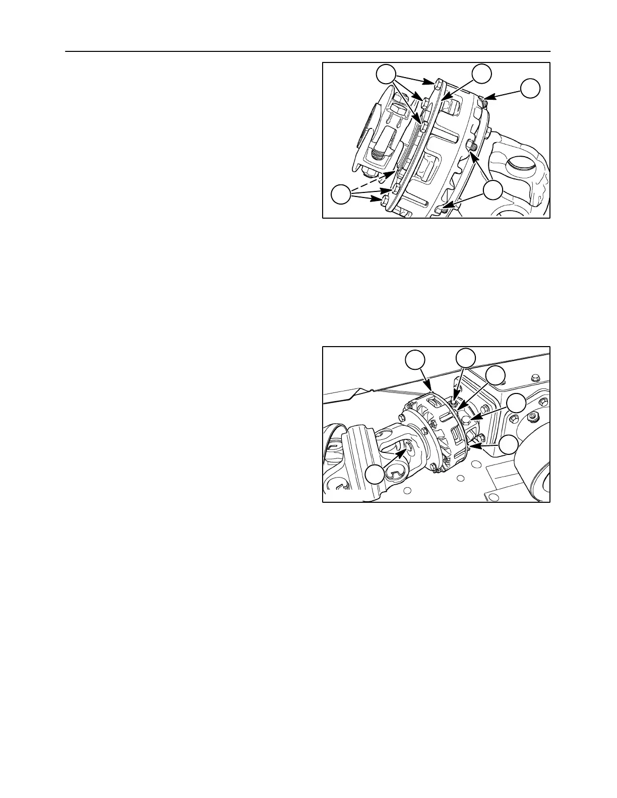
4. Set the compression plate, 1 over the hub
against the outer diameter of the disc spring, and
install six new cap screws, 2, through the
compression plate. Insert new nuts, 3, into the
pockets on the front of the clutch housing and
thread the bolts into the nuts until snug to hold the
assembly together.
5. Tighten all six cap screws evenly until snug, and
then one additional one half turn each to hold the
clutch components securely, and to provide the
setting for running in the clutch.
3
1
50006842
2
2
3
11
Slip Clutch - Installation
The slip clutch must be installed on the unit and run
in before use.
1. Install the drive shaft and slip clutch assembly so
that the two crimped splines align with the slot in
the front of the secondary drive shaft. Slide the
two drive shaft halves together.
2. Slide the slip clutch onto the input shaft as far as
possible. Thread the bolt, 1, inside the slip clutch
hub into the end of the shaft, and tighten as much
as possible to pull the slip clutch hub securely
onto the tapered end of the gearbox shaft.
Tighten the two 1/2 x 3″ Grade 8 cap screws, 2,
and lock nuts at the rear of the clutch to 87 N⋅m
(64 ft-lb).
NOTE: Do not over tighten. The lock nuts are Class
C, and are limited to 87 N
⋅
m (64 ft-lb).
1
2
50012123
3
2
3
3
12