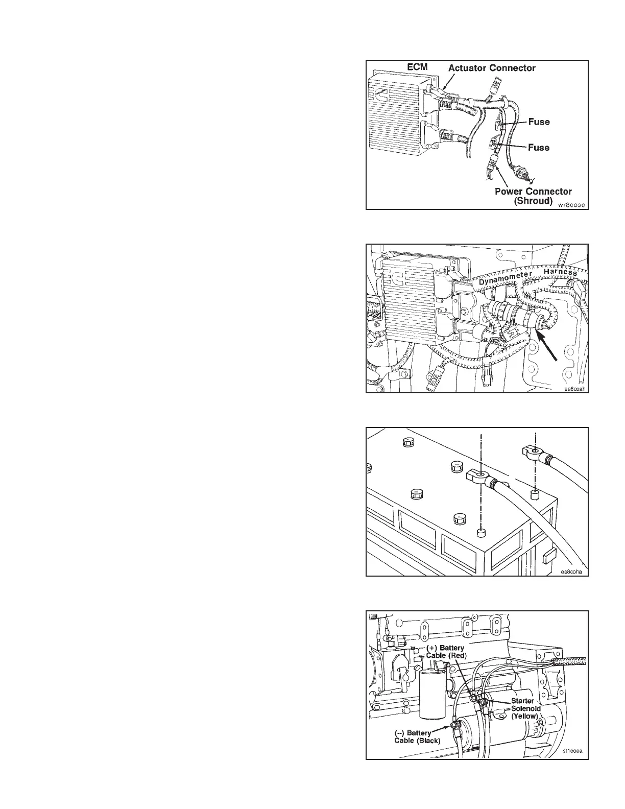
Connect the dynamometer test OEM wiring harness pin
connector to the actuator harness power connector
(shroud).
To save, adjust, and write parameters to and from the
ECM, refer to the CELECT™ Compulink™ Cartridge
Manual, Bulletin No. 3810472.
NOTE: Parameters must be returned to their original value
when the test or run-in is completed.
Connect the dynamometer test OEM wiring harness 9 pin
connector to the sensor harness 9 pin connector.
Connect battery power to the starter.
Connect the dynamometer test OEM wiring harness
starter solenoid lead (yellow) to the starter solenoid. Con-
nect the ground lead (black) to the starter or battery
negative or ground side. Connect the positive 12 VDC
power lead (red) to either the starter or battery positive
(+12 VDC) side.
Engine Testing Engine Dynamometer - Install Engine (8-01)
N14 Page 8-17