105 of 165
M-SV-VT-001-EN Rev. A
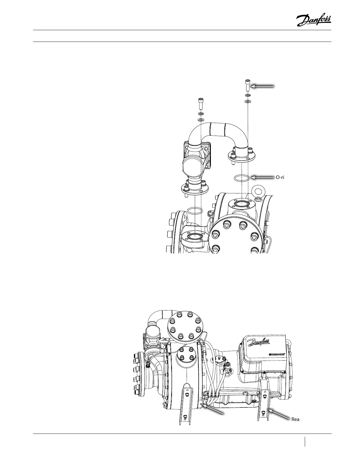
Compressor Components
Figure 127 - IFV Assembly
Removal
O-rings (2 places)
Flange Screws - 70 Nm
(52 ft.lb.) (8 places)
Figure 128 - Support
Locations
Threaded Hole
for U-Channel
Rear Foot
11. The compressor will need to be lifted up to gain clearance for the Volute removal. A 5x5 wood
block under the rear foot and a piece of 6” u-channel under the front. This u-channel needs to be
12” long with a 12.5mm hole drilled in the center. There is a threaded hole under the compressor
where the Volute meets the main compressor housing. Fasten the u-channel to the compressor
with a 12mm bolt (2.5 inches long).
12. Remove the screws at the 10 o’clock and 2 o’clock positions from the Suction Cover.

 Loading...


