151 of 165
M-SV-VT-001-EN Rev. A
OEM Module Components
6.1.1 CIM Verication
1. With power applied to the compressor, connect to the CIM using the SMT and enter the User ID
and Access Code.
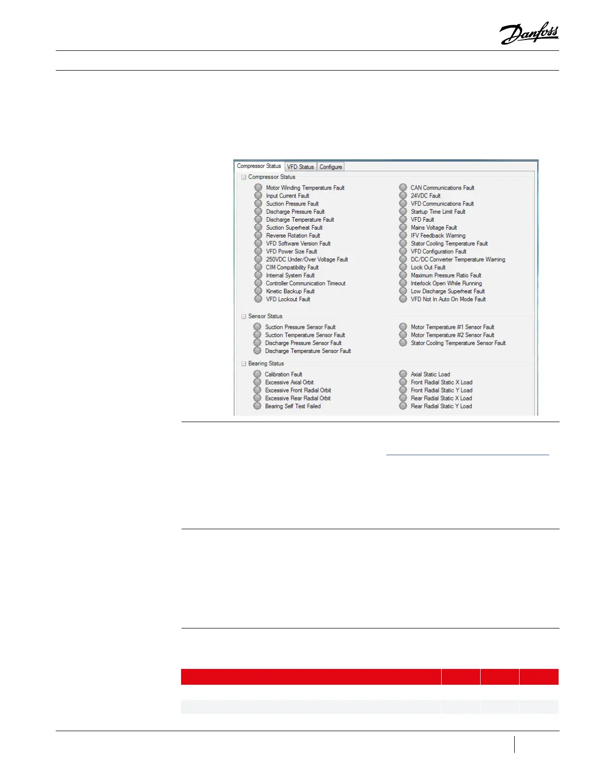
2. Open the Warnings and Faults Tool.
3. Verify that the CIM Compatibility, CAN Communications, and VFD Communications Faults are
not active.
6.1.2 Removal and
Installation
Removal:
1. Isolate the Compressor power as described in the “Electrical Isolation of the Compressor/VFD”
section of this manual.
2. Remove all terminal connectors from the original CIM, leaving all wires connected to the
screw terminals.
3. Remove the CIM from the DIN Rail (or other mounting method).
4. Remove the DIN Rail clip (or other mounting method) from the CIM.
Installation:
1. If used with the original CIM, install the DIN Rail clip (or other mounting method) on the new
CIM, using the original hardware.
2. Mount the new CIM in place.
3. Reinstall all terminal connectors to their proper location.
4. Reconnect power to the compressor.
Description Nm Ft.Lb. In.Lb.
DIN Rail Clip, SHCS, M4x10 3 - 27
Ground Screw 6 - 53
Table 36 - CIM Torque
Specications
6.1.3 Torque
Specications
Figure 199 - Active Alarm/
Fault Viewer

 Loading...


