38 of 165 M-SV-VT-001-EN Rev. A
Compressor Components
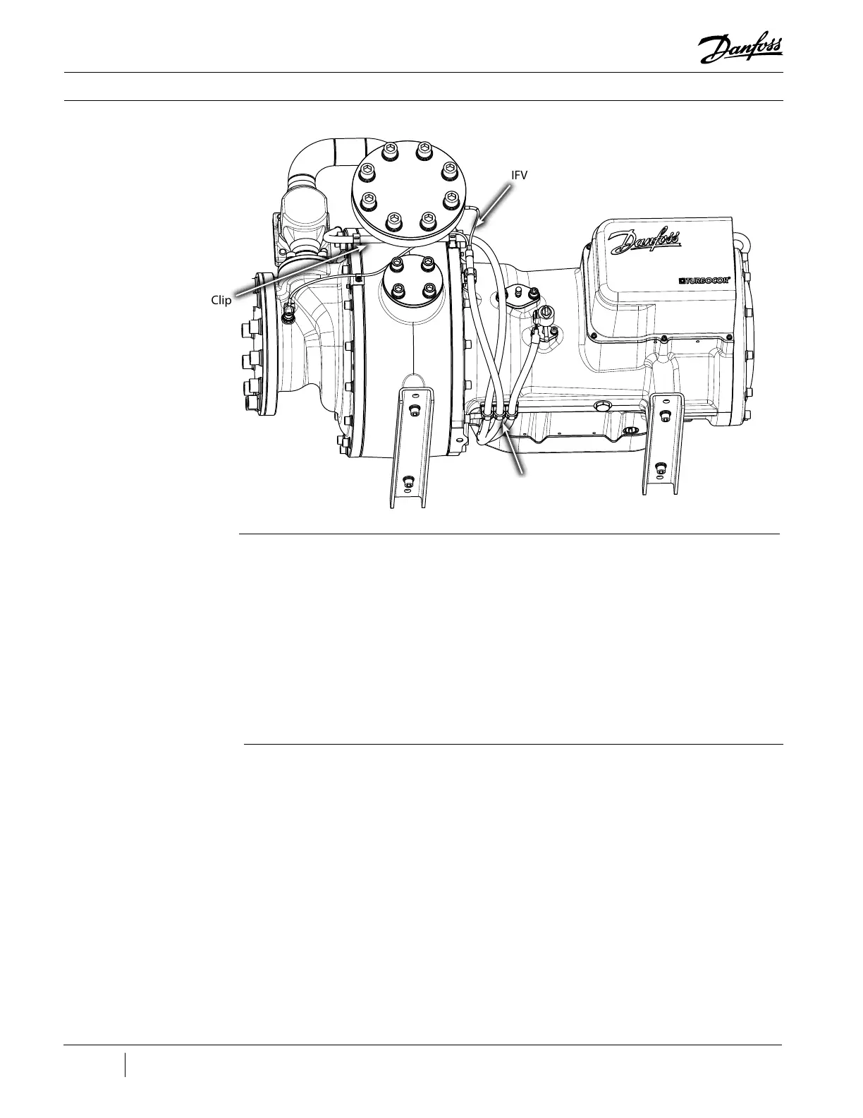
Figure 27 - IFV Cable
Retaining Clips
IFV Cable Installation:
1. Attach the Red (power) and Black (signal) cables to the IFV Valve by turning the collars, located
on the cable ends, in a clockwise rotation.
2. Route the cable from IFV Actuator to the Compressor service side and attach it to the retaining
clips.
3. Plug the connector into J14 (IFV Valve) on the CCM Board.
4. Ensure the connections are tight and secure.
5. Replace the Service Side Cover.
6. Restore power to the Compressor.
IFV Cable Retaining Clip
IFV Cable Retaining Clip
IFV Cable
Retaining Clip
3.2.4.2 Verication
1. Verify proper functionality during Compressor operation.

 Loading...


