122 of 165 M-SV-VT-001-EN Rev. A
Compressor Components
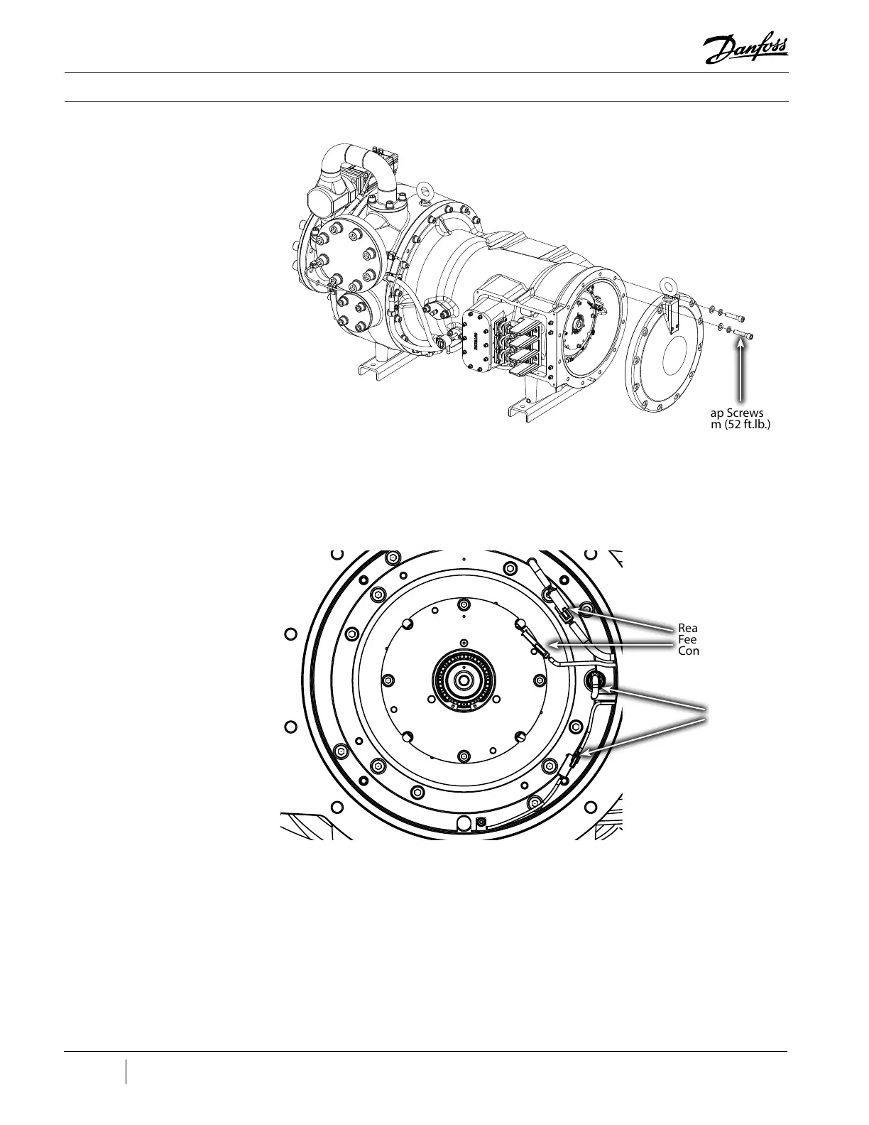
Figure 154 - End Cap
Removal
5. Disconnect the Rear Bearing Sensor and Rear Bearing Power connectors. Refer to Figure 155
(Rear Bearing Sensor and Rear Bearing Power Harness).
Figure 155 - Rear Bearing
Sensor and Rear Bearing
Power Harness
Rear Bearing Power
Feed Through Harness
Connector
Rear Bearing Sensor
Feed Through
Connector
6. Disconnect the external bearing sensor and power cables from the feed throughs.
7. Remove the eight (8) M5 screws holding the feed throughs to the housing.
8. Carefully remove both feed throughs from the housing. Gently pull the internal connectors
through the housing.
9. Remove the O-rings.
End Cap Screws
- 70 Nm (52 ft.lb.)
(12 places)

 Loading...


