140 of 165 M-SV-VT-001-EN Rev. A
Comm
Reset
Fault
Reset
Fault
Status
EV
TX
STATUS
RUN
RX
RS485-1
I-Lock
STAGING VFD COOLING
CAN
Status
24VDC
AUX P/T SENSORS
COMPRESSOR INTERFACE MODULE
CCM CAN
USB
I-Lock
Status
RS485-2
J7
1
1
1 1 1
1
1
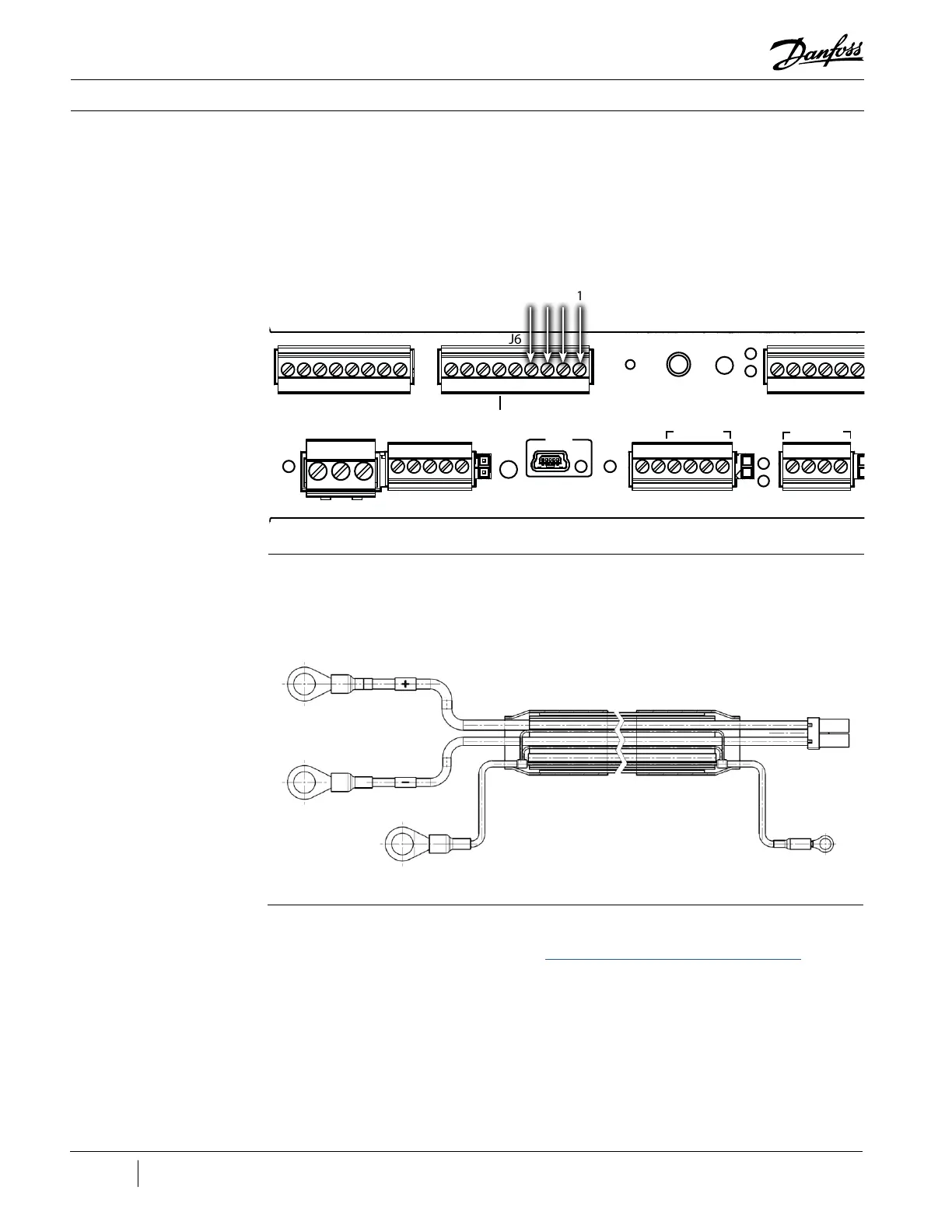
J6 J5
J4J3J2
J1
Variable Frequency Drive Components
Installation:
1. Screw the M12 connector on top of the VFD Pressure Control Valve.
2. Terminate the cable to J6 on the CIM.
3. Secure the cable.
4. Restore power to the VFD.
1243
Figure 180 - CIM
(Revisions A and B)
Wire Diagram
4.6 VFD DC-DC Cable The VFD DC-DC Cable passes High Voltage DC from the VFD to the DC-DC.
Figure 181 - VFD DC-DC
Cable
4.6.1 Removal and
Installation
Removal:
1. Isolate the VFD power as described in the “Electrical Isolation of the Compressor/VFD” section of
this manual.
2. Open the panel containing the DC-DC. Verify the HV DC input from the VFD is below 5 VDC by
checking at VDC+ (J12) and VDC- (J13) test points on the DC-DC with a DC voltage meter.
3. Disconnect (J1) HV DC In connector on the DC-DC Board.

 Loading...


