123 of 165
M-SV-VT-001-EN Rev. A
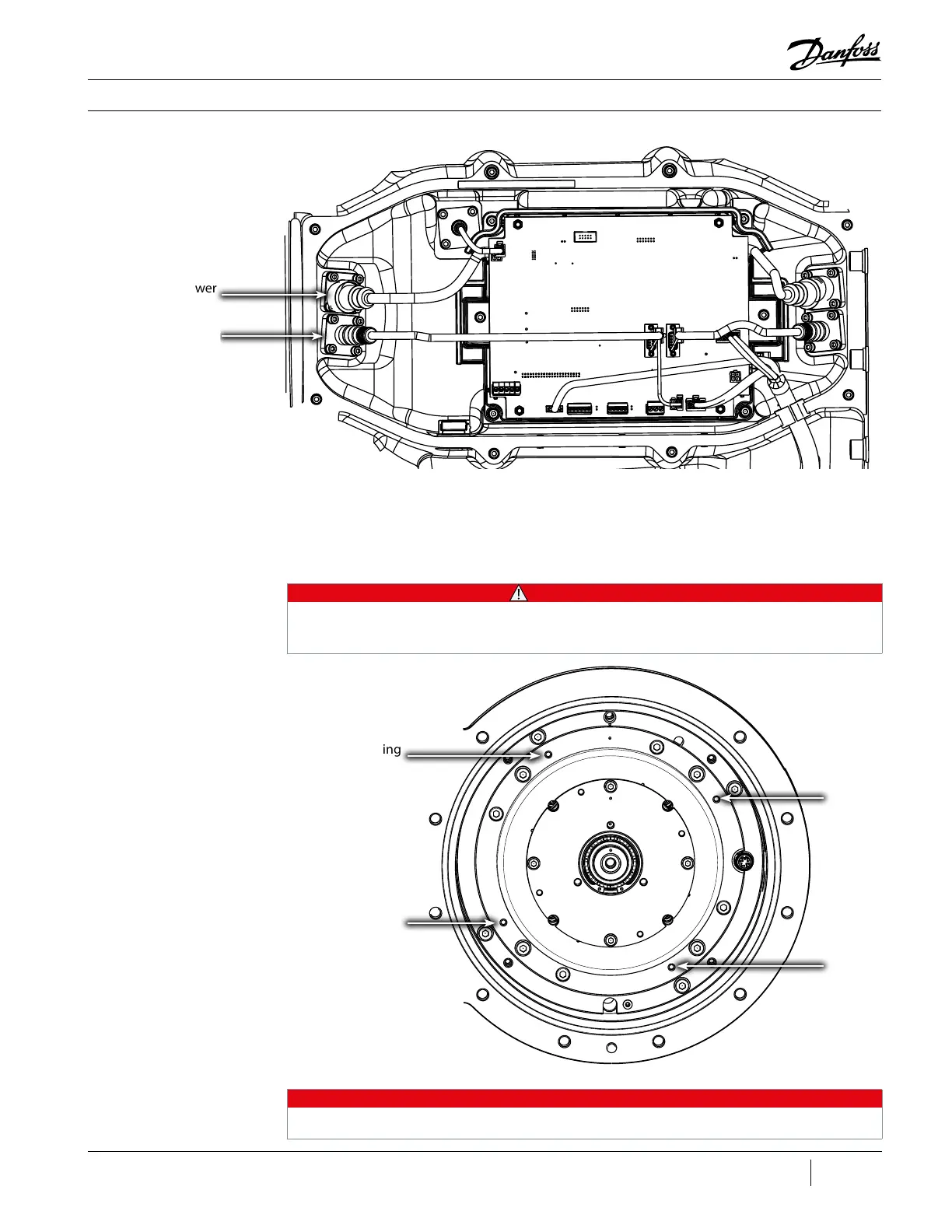
Compressor Components
Figure 156 - Rear Feed
Through Removal
Rear Bearing Sensor
Feed Through
Rear Bearing Power
Feed Through
10. Remove the four (4) screws that secure the Axial Bearing Assembly.
11. Insert four (4) 6 mm jacking screws to aid in the removal of the Axial Bearing Assembly. This will
be required due to the magnetic force keeping the assembly in place. Once the magnetic force
decreases, gently slide away the Axial Bearing Assembly away from the Compressor.
• • • CAUTION • • •
All magnetic parts should be separated and placed in individual bags that can be sealed to prevent
contamination to the parts. Metal debris can and will lead to premature failure of the Compressor
components.
Location for Jacking
Screw (4 places)
Figure 157 - Axial Bearing
Assembly Jacking Screw
Locations
NOTE
For clarity, all wire harnesses were removed from Figure 157 (Axial Bearing Assembly Jacking Screw
Locations).

 Loading...


