95 of 165
M-SV-VT-001-EN Rev. A
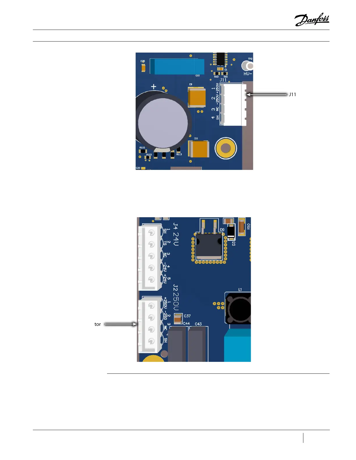
Compressor Components
Figure 111 - PWM J11
Connector (Revisions C
and Later)
4. Remove the cable from the service side.
5. Open the panel containing the DC-DC.
6. Disconnect the 250 V (J2) connector from the DC-DC.
Figure 112 - DC-DC J2
Connector (Revisions C
and Later)
J11 Connector
J2 Connector
Installation (Revisions A and B):
1. Route the cable into the service side.
2. Secure the ground cable to the service side.
3. Insert the connector to J11 on the PWM Board.
4. Secure the cable where it enters the service side.

 Loading...


