81 of 165
M-SV-VT-001-EN Rev. A
Compressor Components
Installation (Revisions A and B):
1. Route the cable into the service side and into the DC-DC panel.
2. Connect the plugs on the CCM Board at 24 VDC (J16) and GND (J24).
3. Terminate the connectors on the DC-DC Board at 24 VDC (J4) and GND (J7).
4. Secure the cables in place.
5. Install the Service Side Cover.
6. Restore power to the Compressor.
Installation (Revisions C and Later):
1. Route the cable into the service side and into the DC-DC panel.
2. Connect the plug to the J4 connector on the CCM Board.
3. Terminate the connector on DC-DC Board at 24 VDC (J4).
4. Secure the cables in place.
5. Install the Service Side Cover.
6. Restore power to the Compressor.
3.7.1.4.2 DC-DC-CIM 24V
Cable Verication
After power is applied to the Compressor, ensure the LEDs on the CIM are illuminated and
communication is established.
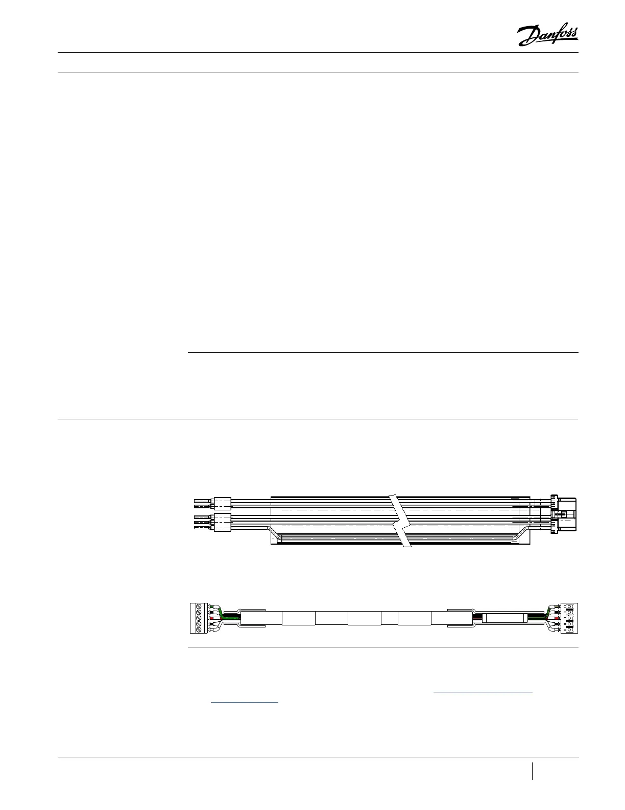
3.7.1.5 CCM-CIM Cable The CCM-CIM Cable provides a connection for communication between the CCM and the CIM.
Figure 85 - CCM-CIM Cable
(Revisions A and B)
Figure 86 - CCM-CIM Cable
(Revisions C and Later)
3.7.1.5.1 Removal and
Installation
Removal:
1. Isolate the Compressor and VFD power as described in the “Electrical Isolation of the
Compressor/VFD” section of this manual.
2. Remove the cover to the controls panel.
3. Disconnect the J2 CCM CAN terminals from the CIM.

 Loading...


