76 of 165 M-SV-VT-001-EN Rev. A
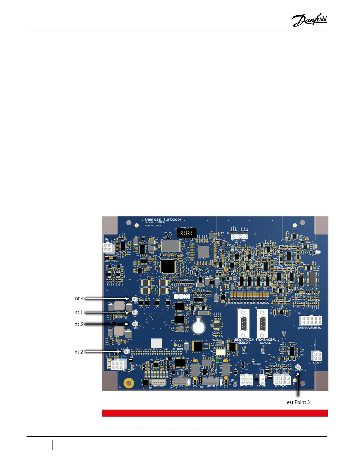
Test Point 3
3.7.1.2.2 CCM
Connections
Compressor Components
The CCM receives the following voltages from the VTT VFD:
• 5 VDC
• 15 VDC
• 24 VDC
• J12 – Motor Temperature – upper left
• J16 – 24V DC In and J24 ground– lower left
• J15 – Motor Cooling EEV – bottom left
• J4 – VFD Communication – bottom left
• J17 – CIM Communication – bottom middle
• J7 – 24 V DC Out to CIM and J11 Ground – bottom right
• J10 and J6 – Bearing Sensor Cables – center right
• J1 – ST RTD – bottom right
• J14 – IFV Valve – bottom right
• J13 – Economizer EEV (if available) – lower right
• J8 – Suction/Discharge P/T sensors – mid right
Figure 73 - CCM
Electrical Connections
and Test Points
(Revisions A and B)
Test Point 1
Test Point 4
Test Point 2
Test Point 5
NOTE
The location is the same for the Test Points for all revision CCM Board assemblies.

 Loading...


