154 of 165 M-SV-VT-001-EN Rev. A
Strain Relief
Compressor Removal and Installation
7. Remove the cable gland that secures the motor power cable conduit to the Conduit Bracket.
8. Reinstall the Motor Power Cover.
9. Remove the Service Side Cover.
10. Disconnect the interface cables, CIM, DC-DC, and VFD Module to the relevant connection points
on the CCM and PWM.
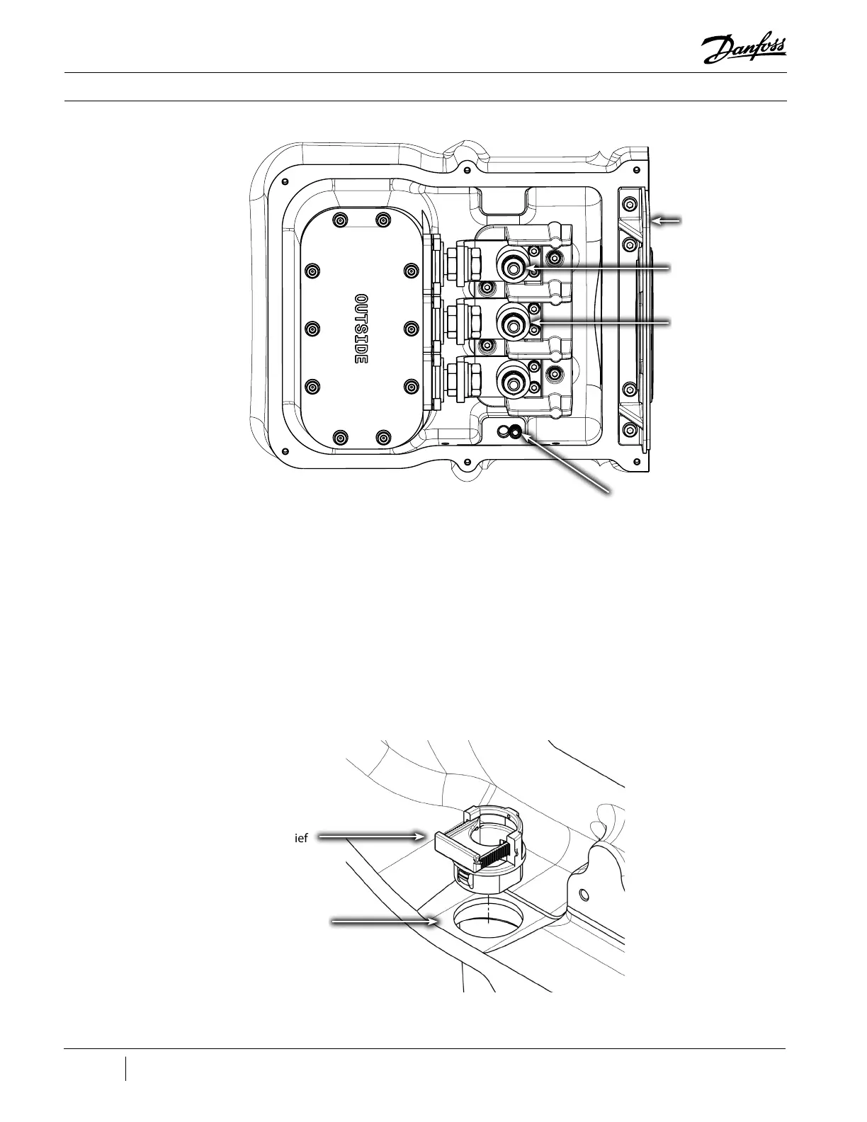
11. Remove the strain relief from the compressor housing as shown in Figure 202 (Strain Relief).
Figure 201 - Compressor
Power Cable Removal
Figure 202 - Strain Relief
Power Cable Nuts,
Torque to 10 Nm
(8 ft.lb.) (3 places)
Copper Spacer,
Washer, & Lock
Washer (3 places)
Ground Post,
Torque nut to 20 Nm
(15 ft.lb.)
Compressor Housing
Bottom of Service
Side
Conduit Bracket

 Loading...


