69 of 165
M-SV-VT-001-EN Rev. A
Compressor Components
3.4 Service Side
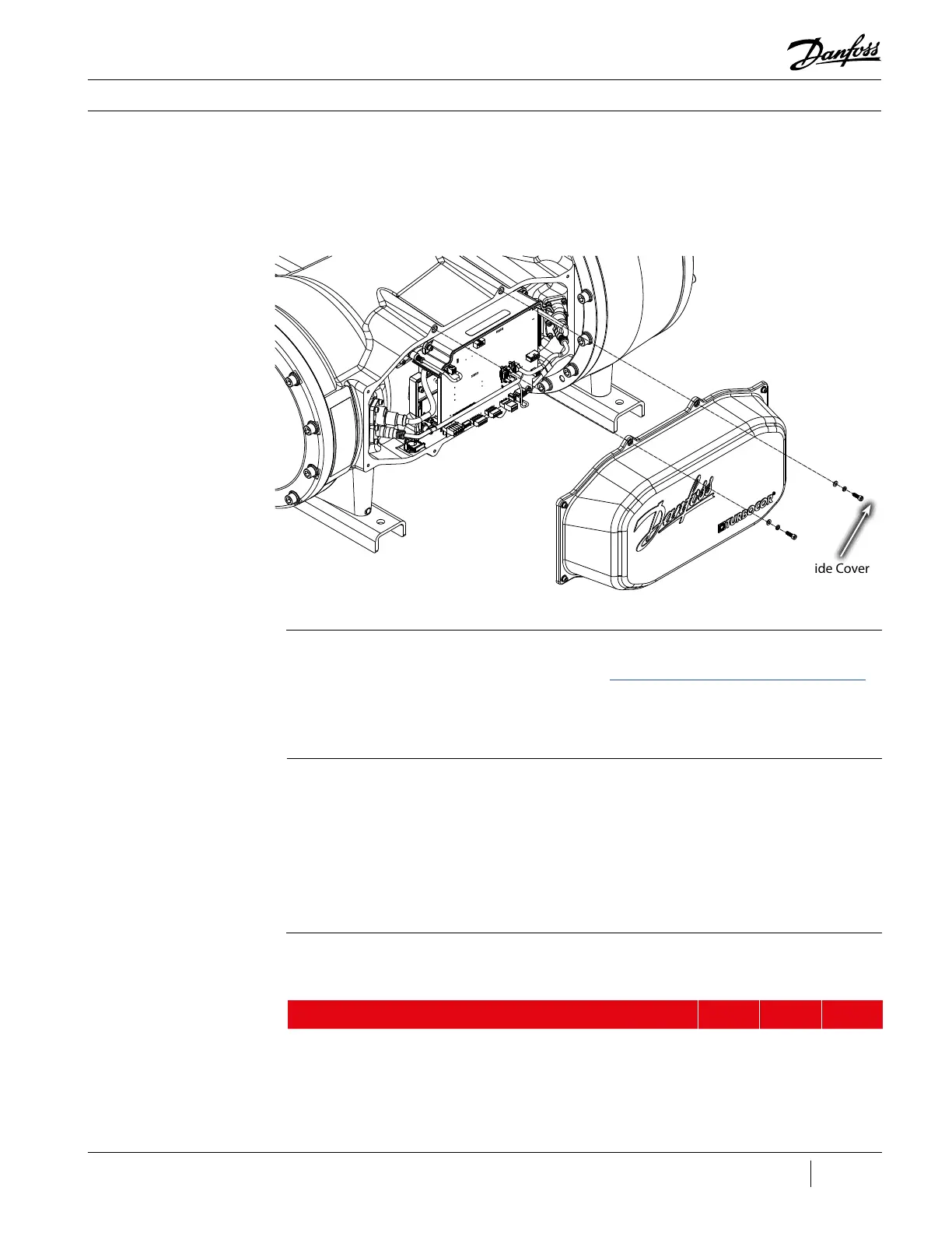
3.4.1 Service Side Cover The Service Side Cover provides protection for the PWM, CCM, feed throughs, and cabling.
Figure 63 - Service Side
Cover
3.4.1.1 Removal and
Installation
Service Side Cover Removal:
1. Isolate the Compressor power as described in the “Electrical Isolation of the Compressor/VFD”
section of this manual.
2. Remove the eight (8) M5x16 screws that hold the Service Side Cover in place.
3. Remove the Service Side Cover.
Service Side Cover Installation:
1. Verify all contact surfaces are clean and dry. If not, clean with a lint-free cloth.
2. Place the gasket on the sealing surface of the cover.
3. Place the cover over the service side.
4. Install the eight (8) M5x16 screws to secure the Service Side Cover.
5. Restore power to the Compressor.
Description Nm Ft.Lb. In.Lb.
Service Side Cover, SHCS, M5x16 6 - 53
Table 21 - Motor
Power Cover Torque
Specications
Service Side Cover
Screws
Torque to 6 Nm
(53 in.lb.) (8 places)
3.4.1.2 Torque
Specications

 Loading...


