37 of 165
M-SV-VT-001-EN Rev. A
IFV Cable Removal:
1. Isolate the Compressor power as described in the “Electrical Isolation of the Compressor/VFD”
section of this manual.
2. Disconnect the Red (power) and Black (signal) cables from the IFV Valve by turning the collars,
located on the cable ends, in a counter-clockwise rotation.
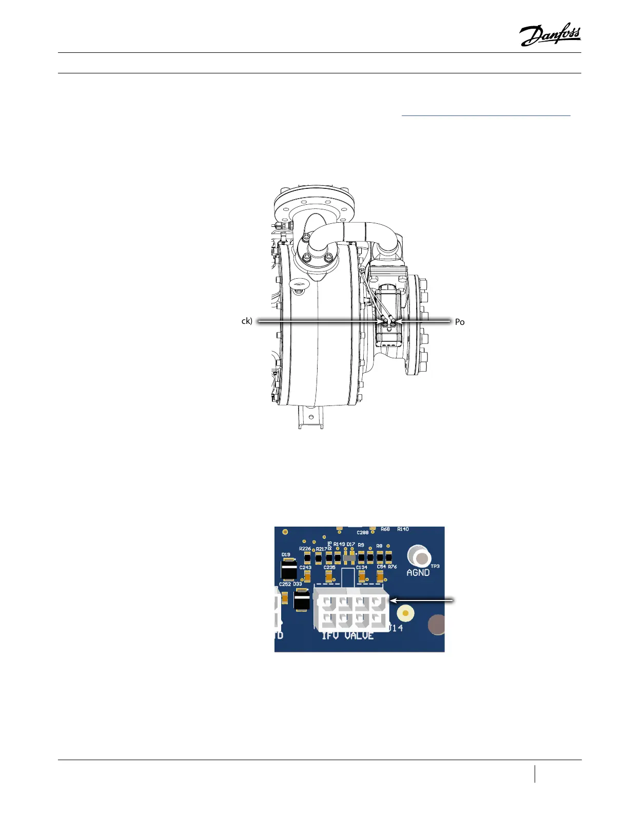
Figure 26 - J14 CCM Board
Connector
J14 Connector
Compressor Components
3.2.4.1 Removal and
Installation
Figure 25 - IFV Cable
Connection
Power Cable (Red)
Signal Cable (Black)
3. Remove the Compressor Service Side Cover.
4. Locate J14 (IFV Valve) on the CCM Board and remove the connector. Refer to Figure 26 (J14 CCM
Board Connector).
5. Remove the cable from the retaining clips. Refer to Figure 27 (IFV Cable Retaining Clips).

 Loading...


