116 of 165 M-SV-VT-001-EN Rev. A
Compressor Components
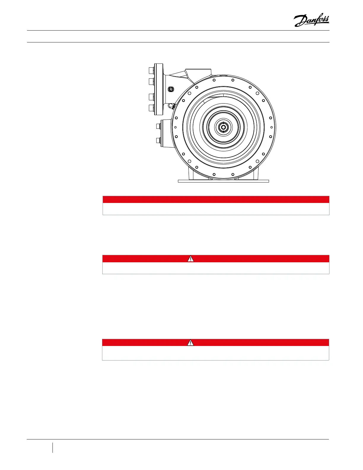
Figure 148 - Volute Torque
Pattern
9
1
2
4
6
8
5
10
7
3
11
12
14
15
13
16
18. Install the First Stage Impeller and align it to the witness marks. This will require the use of a heat
gun to heat up the impeller. Do not use a torch!
19. Install the First Stage Impeller bolt and torque to specification.
• • • CAUTION • • •
This is a left-hand thread bolt; to install, it must be tightened by turning it to the left.
20. Verify all contact surfaces are clean and dry between the Suction Housing and the Volute. If not,
clean with a lint-free cloth.
21. Apply Super-O-Lube to the new O-ring and then fit it into the O-ring groove on the Suction
Housing.
22. Insert the Short Guide Pins in the 10 o’clock, 2 o’clock, and 6 o’clock positions on the Volute.
23. Carefully install the Suction Housing.
• • • CAUTION • • •
Be sure to locate the Short Guide Pin at 3 o’clock position to ensure the IFV pipe is lined up properly.
24. Prepare all 16 screws with the lock washer and flat washer.
25. Finger tighten at least four (4) screws before removing the guide pins.
26. Remove the guide pins and finger tighten the remaining screws.
NOTE
Figure 148 (Volute Torque Pattern) has the Volute removed in order to provide better clarity.

 Loading...


