47 of 165
M-SV-VT-001-EN Rev. A
Compressor Components
3.2.8.1 Removal and
Installation
EXV Cable Removal:
1. Isolate the Compressor power as described in the “Electrical Isolation of the Compressor/VFD”
section of this manual.
2. Remove the Service Side Cover.
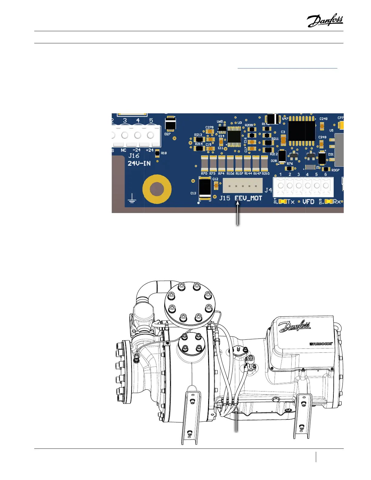
3. Remove connector J15 EEV_MOT from the CCM.
Figure 40 - CCM J15
Connector
4. Remove the Valve Actuator from the EXV on the discharge side of Compressor.
5. Route the cable out of the service side.
6. Release the cable from the retaining clip located underneath the Compressor. Refer to Figure 36
(EXV Cable Retaining Clip) for the exact location of the clip.
Figure 36 - EXV Cable
Retaining Clip
EXV Cable Retaining
Clip

 Loading...


