145 of 165
M-SV-VT-001-EN Rev. A
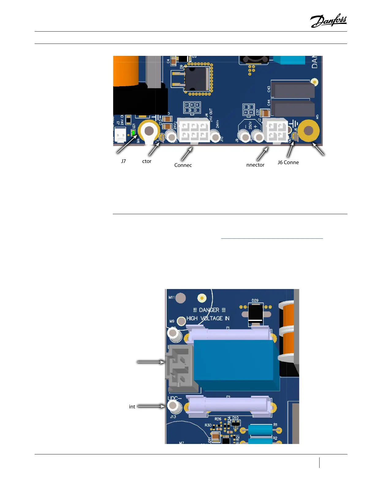
Figure 187 - DC-DC J2 and
J4 Connections
4. Disconnect the grounding wires from M4, M5, J6, and J7.
5. Remove the securing hardware holding the DC-DC frame to the panel.
6. Remove the DC-DC from the panel.
J6 Connector
J7 Connector
M4 Ground
M5 Ground
Removal (Revisions C and Later):
1. Isolate the VFD power as described in the “Electrical Isolation of the Compressor/VFD” section of
this manual.
2. Open the panel containing the DC-DC. Verify the HV DC input from VFD is below 5 VDC by
checking at VDC+ (J12) and VDC- (J13) test points on DC-DC with a DC voltage meter.
3. Disconnect the HV DC input cable from J1; 24 VDC output cable from J4; and 250 VDC output
cable from J2.
Figure 188 - DC-DC J1
Connection and J12 -J13
Test Points
J13 Test Point
OEM Module Components
J12 Connector
J4 Connector
J2 Connector

 Loading...


