91 of 165
M-SV-VT-001-EN Rev. A
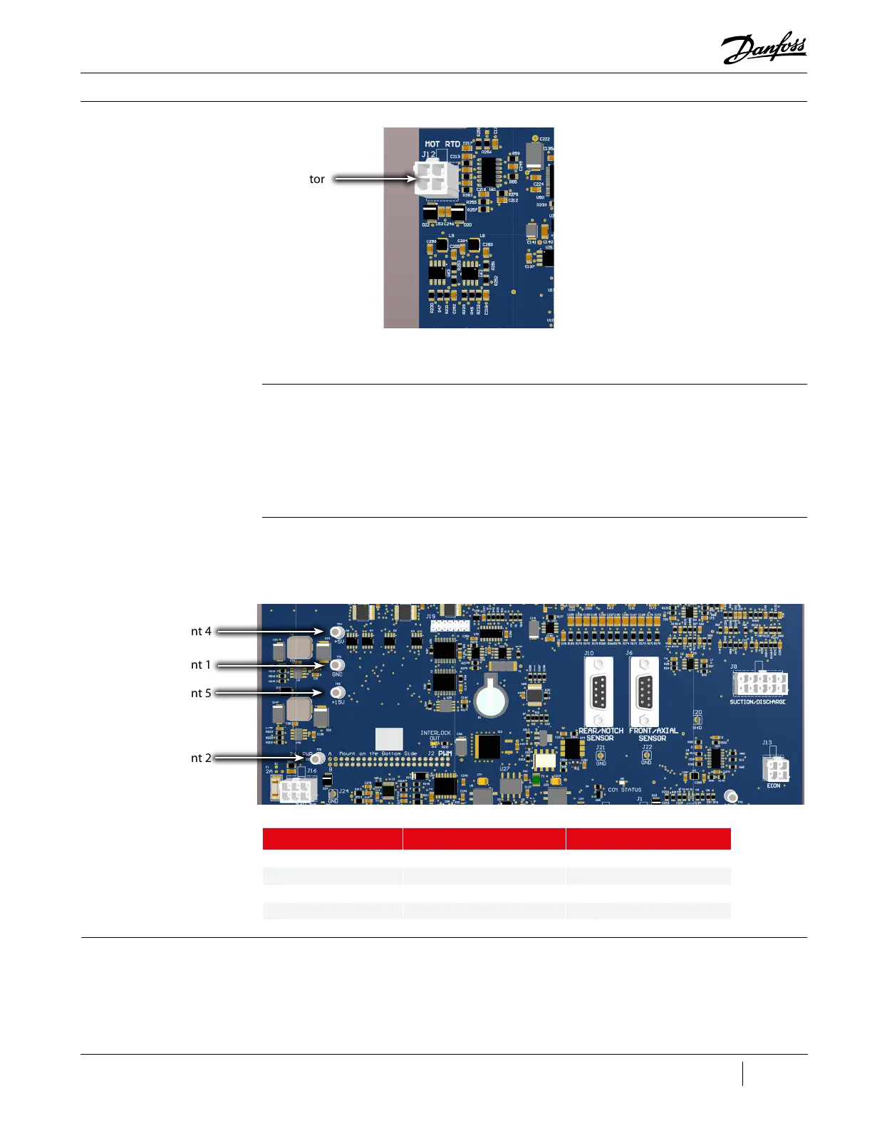
Figure 104 - CCM J12
Connection
Compressor Components
4. Locate the feed through for the motor temp sensor and remove the connector.
Installation:
1. Install the sensor on the feed through.
2. Attach the connector to MOT RTD (J12) on the CCM Board.
3. Install the Service Side Cover.
4. Restore power to the Compressor.
With power applied to the Compressor, using a DC voltage meter, place the negative (-) test lead in the
TP1 - GND test point and verify the voltages at the test points listed in Table 25 (CCM Test Point Values).
3.7.1.9.2 Motor
Temperature Sensor
Cable Verication
Table 25 - CCM Test Point
Values
Test Point Number Test Point Voltage Value DC Voltage Range
TP2 24+ 21.6-26.4
TP5 15+ 13.5-16.5
TP4 5+ 4.5-5.5
TP1 Ground
3.7.1.10 PWM
1. The PWM Board is mounted parallel to the CCM with a heat sink connected to the Compressor
housing.
2. The PWM Board provides circuitry with the following functionalities:
• Supplies current to the axial and radial magnetic bearing actuators
• Provides bearing current sensor feedback
J4 Connector
Test Point 1
Test Point 4
Test Point 5
Test Point 2

 Loading...


