83 of 165
M-SV-VT-001-EN Rev. A
Compressor Components
Installation:
1. Route cable between the CCM and CIM.
2. Connect cable to J2 CCM/CAN termination on the CIM.
3. Connect opposite end of cable to J17 CIM on CCM Board.
4. Secure cables in location.
5. Reinstall the covers.
6. Restore power to the Compressor and verify proper operation.
3.7.1.5.2 CCM-CIM Cable
Verication
1. With Power applied to the Compressor, connect to the CIM using the SMT and enter the User ID
and Access Code.
2. Open the Warnings and Faults Tool.
3. Verify that the CIM Compatibility, CAN Communications and VFD Communications Faults are
not active.
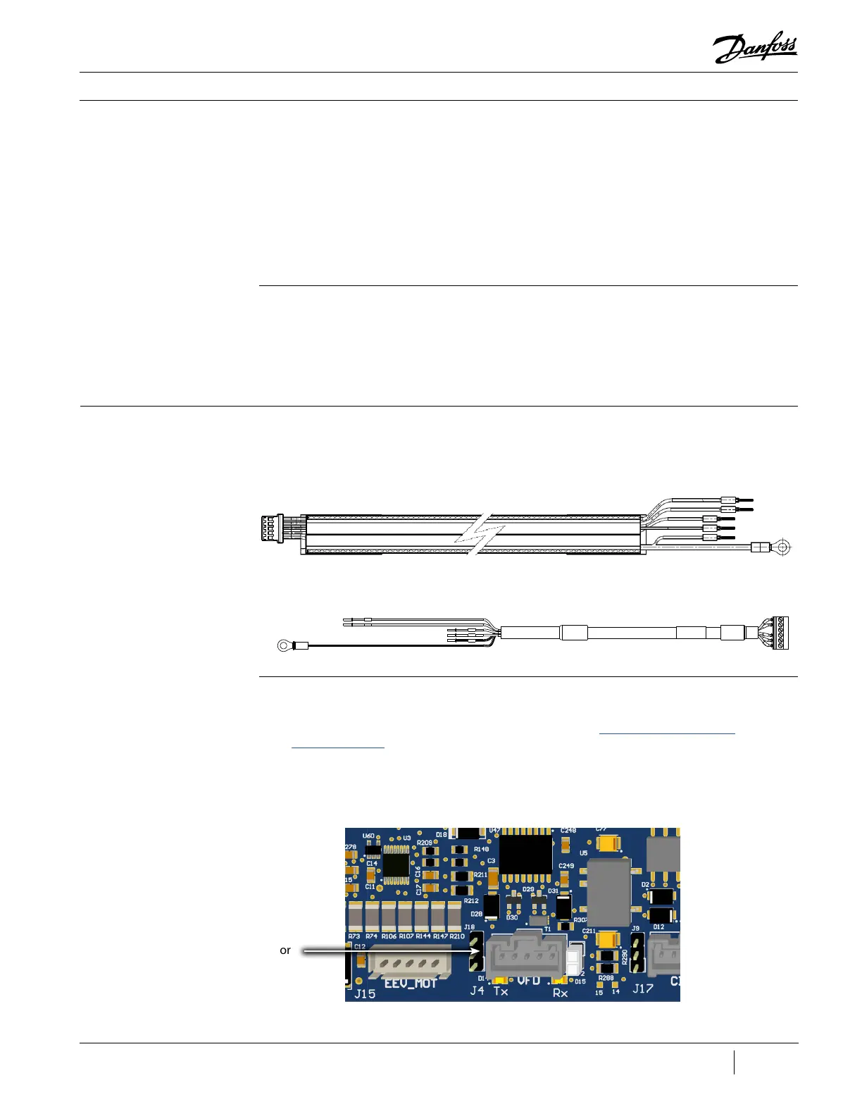
3.7.1.6 CCM-VFD Cable The VFD Cable provides a connection for communication between the CCM and the VFD.
Figure 90 - CCM-VFD Cable
(Revisions A and B)
Figure 91 - CCM-VFD Cable
(Revisions C and Later)
3.7.1.6.1 Removal and
Installation
Removal:
1. Isolate the Compressor and VFD power as described in the “Electrical Isolation of the
Compressor/VFD” section of this manual.
2. Remove the Compressor Service Side Cover.
Figure 92 - J4 Connector
(Revisions A and B)
J4 Connector

 Loading...


