30 of 165 M-SV-VT-001-EN Rev. A
Compressor Components
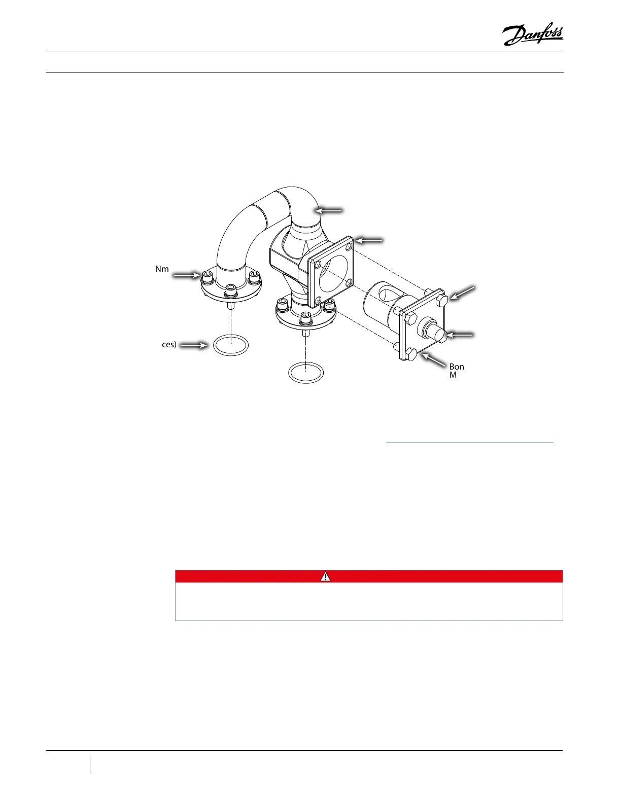
Figure 17 - IFV Pipe
Assembly
3.2 External Components
The IFV directs a small fraction of the ow from the second stage Volute exit to the inlet of the rst
stage diuser through the IFV Pipe.
3.2.1 IFV Pipe Assembly
3.2.1.1 Removal and
Installation
IFV Pipe Removal:
1. Isolate the Compressor power as described in the “Electrical Isolation of the Compressor/VFD”
section of this manual.
2. Isolate the Compressor and recover refrigerant.
3. Remove the wires from the IFV Actuator by turning the collar, located on the cable end, in a
counter-clockwise rotation
4. Remove the three (3) set screws from the IFV Actuator base where it attaches to the Bonnet/
Function Module.
5. Remove the IFV Actuator from the Bonnet/Function Module.
6. Loosen all eight (8) screws from the suction and discharge side of the IFV pipe assembly.
IFV Pipe Assembly
ICM Bolts - 100 Nm (74
ft.lb.) (4 places)
ICM Adapter/Valve
Stem
Bonnet/Function
Module
O-rings (2 places)
Flange Screws - 70 Nm
(52 ft.lb.) (8 places)
• • • CAUTION • • •
Failure to loosen all eight (8) screws rst may lead to damaging the threads in the Suction Housing
and /or the Volute. Do not attempt to remove the screws from only one (1) side while the other side
is still secure!
7. Remove the eight (8) screws from the suction and discharge side of the IFV pipe assembly.
8. Remove the IFV pipe assembly and O-rings.
ICM Body

 Loading...


