94 of 165 M-SV-VT-001-EN Rev. A
Compressor Components
4. Remove the 250V PWM ground wire from the service side.
5. Remove the cable from the service side.
6. Open the panel containing the DC-DC.
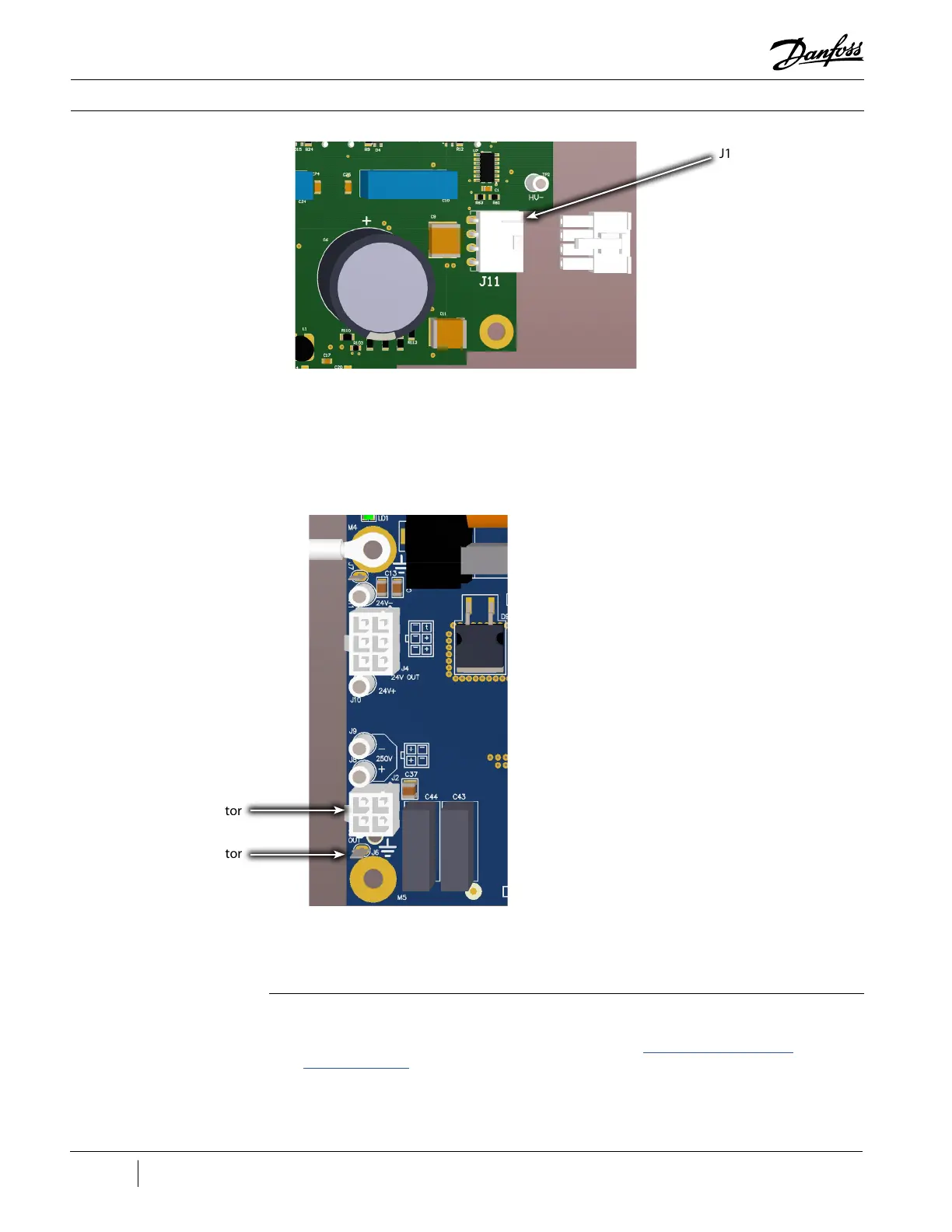
7. Disconnect the 250 V (J2) clip from DC-DC.
Figure 110 - DC-DC J2 and
J6 Connector (Revisions A
and B)
8. Disconnect the 250V DC-DC ground wire from the DC-DC.
9. Remove the cable from the DC-DC panel.
Removal (Revisions C and Later Cables):
1. Isolate the Compressor and VFD power as described in the “Electrical Isolation of the
Compressor/VFD” section of this manual.
2. Remove the Service Side Cover.
3. Disconnect the J11 connector from the PWM.
J2 Connector
J6 Connector
Figure 109 - PWM J11
Connector (Revisions A
and B)
J11 Connector

 Loading...


