63 of 165
M-SV-VT-001-EN Rev. A
Compressor Components
3.3.6.1 Connections
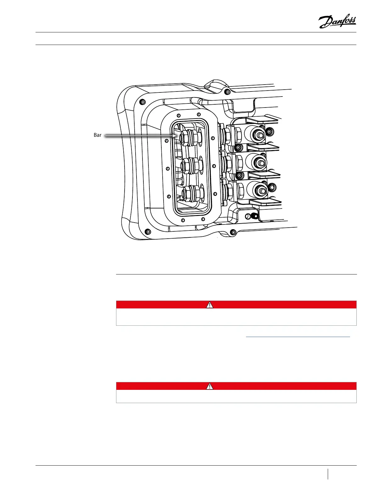
Refer to Figure 57 (Connection to Stator) to identify connections to the motor.
Figure 57 - Connection
to Stator
3.3.6.2 Motor Verication Stator Insulation Verication
• • • CAUTION • • •
Do not attempt to perform an insulation test on a component under vacuum. This can cause
insulation breakdown or failure during the testing process.
1. Isolate the Compressor power as described in the “Electrical Isolation of the Compressor/VFD”
section of this manual.
2. Remove the Motor Power Cover.
3. Remove the three (3) M10 nuts and flat washers off the top of the copper spacers.
4. Remove the motor power cables.
• • • CAUTION • • •
A faulty Stator can cause the Inverter to fail.
5. Using a mega-ohm meter set for 1000 VDC measurements, connect the red (+) mega-ohm
meter lead to one of the three (3) Motor Bus Bars and the black (-) mega-ohm meter lead to
the Compressor housing. The measured value should be greater than 100 mega-ohms . If the
measured value does not correspond to the expected resistance, then the Stator insulation is
faulty and the Compressor needs to be replaced.
6. Repeat Step five (5) for the remaining two (2) Motor Bus Bars to ensure all windings are intact.
Motor Bus Bar
(3 places)

 Loading...


