86 of 165 M-SV-VT-001-EN Rev. A
Compressor Components
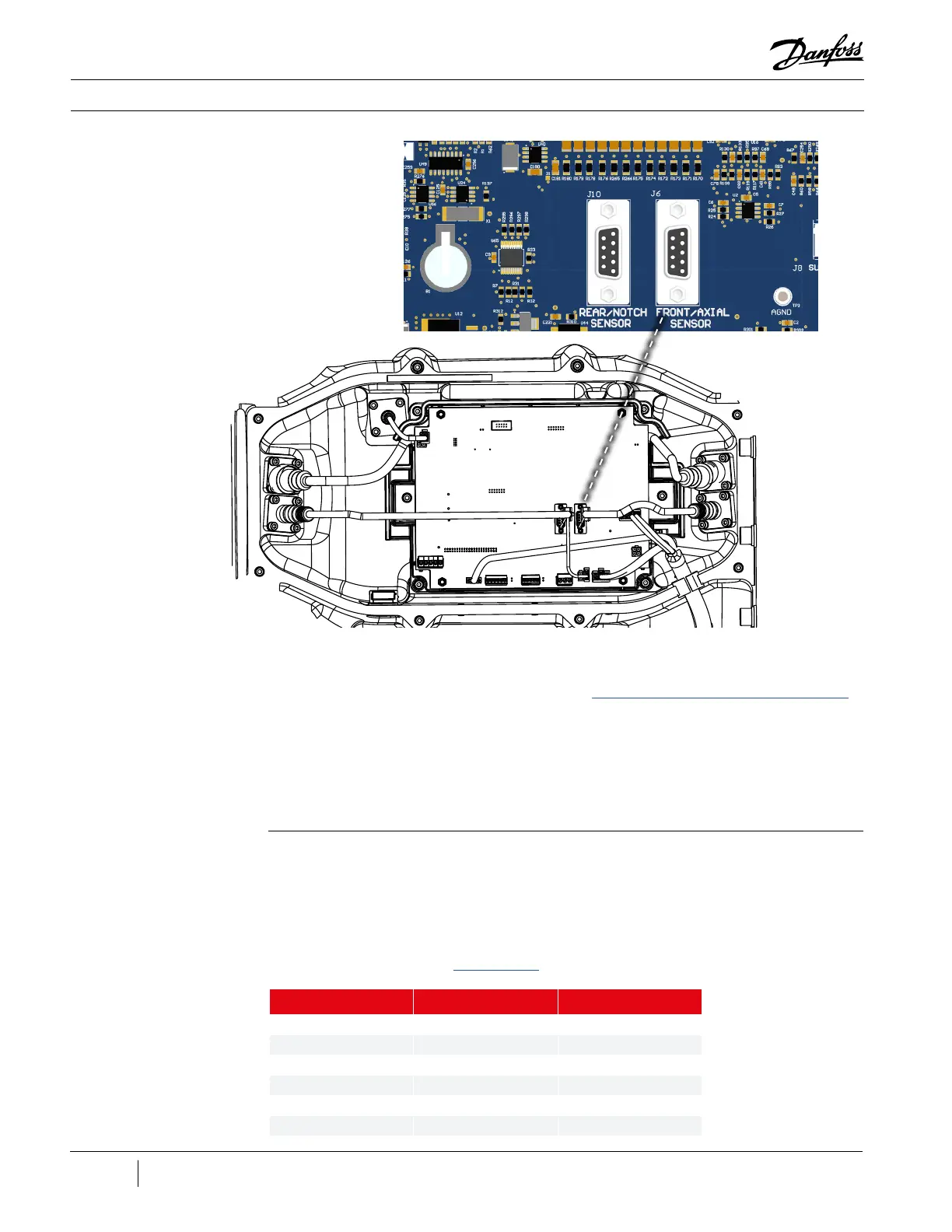
Figure 96 - Front Bearing
Sensor Connections
Installation:
1. Isolate the Compressor power as described in the “Electrical Isolation of the Compressor/VFD”
section of this manual.
2. Connect the 9-pin connector into J6 on the CCM Board.
3. Twist and push to connect the sensor cable connection to the feed through.
4. Install the Service Side Cover.
5. Restore power to the Compressor.
1. Using a multimeter set for resistance measurements, check the resistance at the 9-pin connector
to verify connection to the sensor ring. Refer to Table 23 (Front Bearing Sensor Pin Verification)
for the resistance specifications. Refer to Figure 97 (9-Pin Connector) for the pinout.
2. If the results do no match the specifications listed, remove the cable and check the resistances at
the feed through. Refer to Figure 98 (Feed Through Connector) for the pinout.
3. If the results still do not match the listed specifications, the feed through will need to be tested
for continuity. Refer to the “Rear Bearings” section for details on how to remove the feed through.
3.7.1.7.2 Front Bearing
Sensor Cable Verication
Table 23 - Front Bearing
Sensor Pin Verication
Pins Sensor Type Resistance
6-7 Radial 2.0 Ω to 3.5 Ω
6-8 Radial 2.0 Ω to 3.5 Ω
9-1 Rotation 2.0 Ω to 3.5 Ω
1-4 Rotation 2.0 Ω to 3.5 Ω
2-3 Radial 2.0 Ω to 3.5 Ω
3-5 Radial 2.0 Ω to 3.5 Ω

 Loading...


