108 of 165 M-SV-VT-001-EN Rev. A
Compressor Components
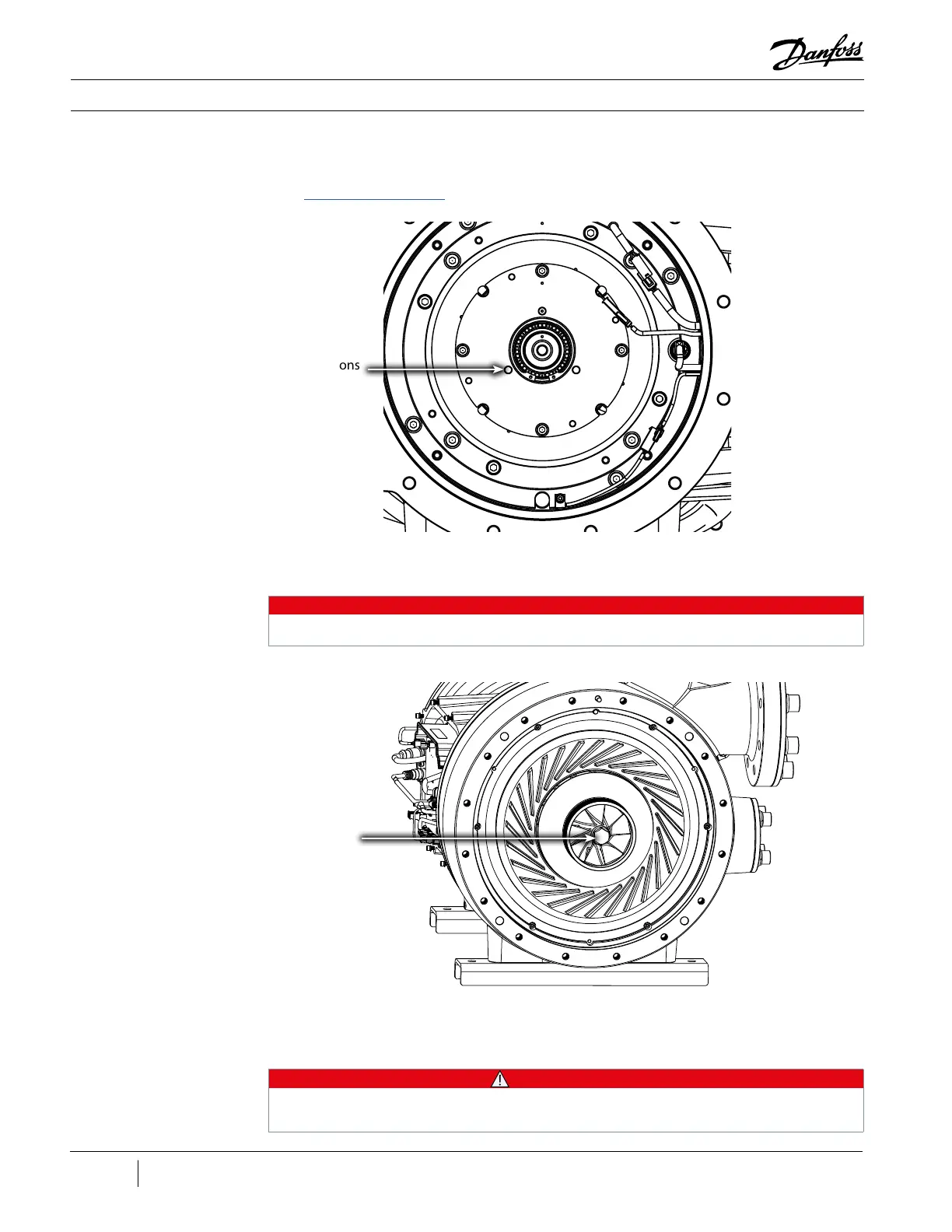
Figure 133 - Shaft Dowel Pin
Placement
Dowel Pin Locations
(3 Places)
Figure 134 - Impeller Bolt
NOTE
This is a left-hand thread; to remove, the bolt must be loosened by turning it to the right.
• • • CAUTION • • •
• Note the alignment/orientation of all uid module components prior to removal
• Do not use anything with a ame (e.g., torch) to heat up the impeller
First Stage Impeller Bolt
- 100 Nm (74 ft.lb.)
21. Install three (3) Shaft Bolt Torquing Pins in the three (3) holes in the Axial Bearing Assembly. It
will be necessary to turn the shaft bolt on the front of the compressor in order to engage the
pins. These pins will then hold the shaft in place for the removal of the shaft bolt. Refer to the
“Shaft Bolt Torquing Pin” example in Appendix B.
22. Remove the shaft bolt from the First Stage Impeller.
23. Remove the First Stage Impeller. This will require the use of a heat gun to heat up the impeller.
Do not use a torch!

 Loading...


