139 of 165
M-SV-VT-001-EN Rev. A
Variable Frequency Drive Components
4.5.2 VFD Pressure
Control Valve Removal
and Installation
Removal:
1. Isolate the VFD power as described in the “Electrical Isolation of the Compressor/VFD” section of
this manual.
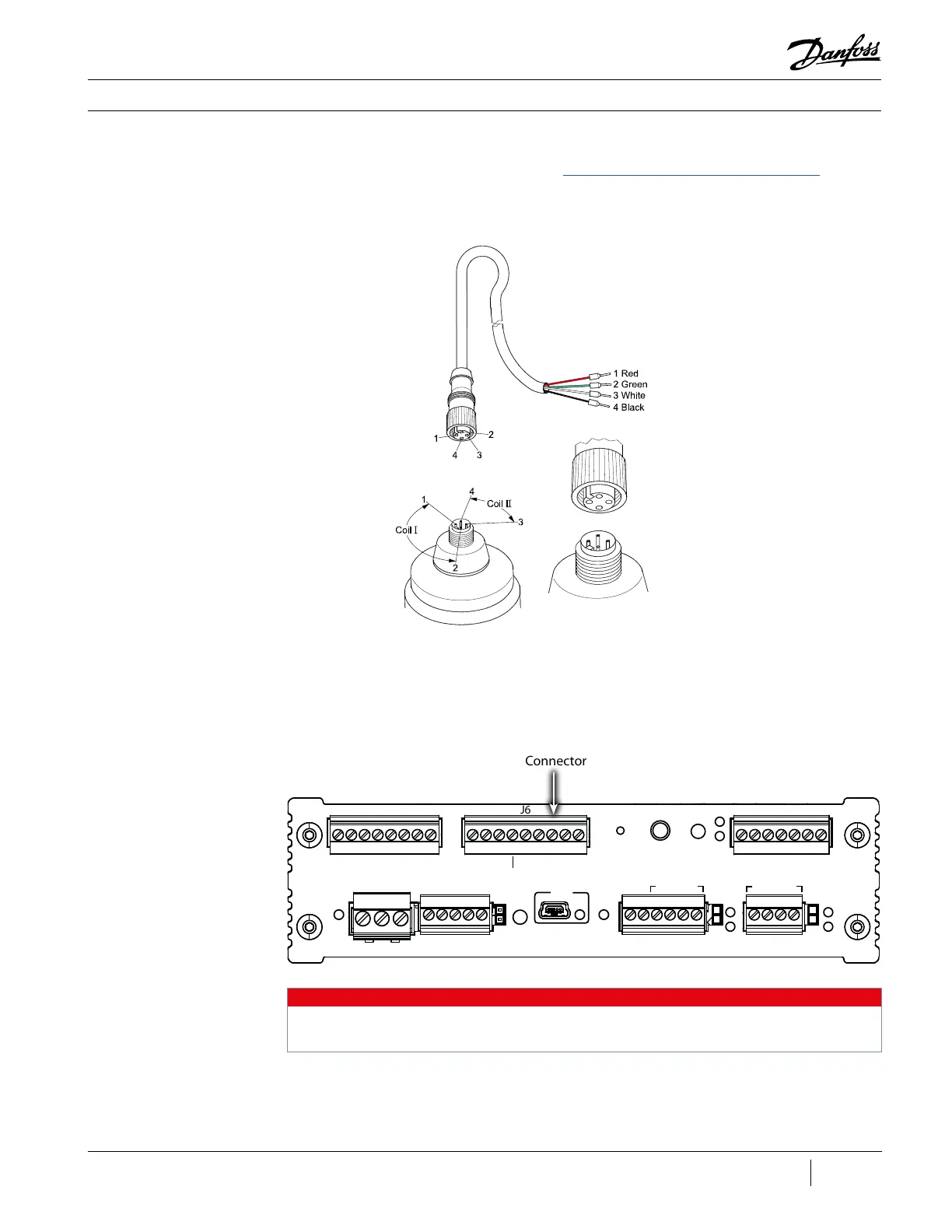
2. Unscrew the M12 connector from the top of the VFD cooling valve.
Figure 178 - VFD Pressure
Control Valve M12
Connection
3. Remove the controls panel cover where CIM is located.
4. Remove VFD Pressure Control Valve Cable from the CIM at J6 (VFD Cooling). The numbers
referenced in Figure 180 (CIM (Revisions A and B) Wire Diagram) correspond to the numbers/
colors listed in Figure 178 (VFD Pressure Control Valve M12 Connection).
Figure 179 - CIM (Revisions
A and B) J6 Connection
J6 Connector
NOTE
A gure representing CIM Revision C is not shown. The order of connectivity is the same between the
two (2)revisions.
5. Remove the cable.
Comm
Reset
Fault
Reset
Fault
Status
EV
TX
STATUS
RUN
TX
RX
RX
RS485-1
I-Lock
STAGING VFD COOLING
CAN
Status
24VDC
AUX P/T SENSORS
COMPRESSOR INTERFACE MODULE
POWER
CCM CAN
USB
I-Lock
Status
RS485-2
J7
1
1
1 1 1
1
1
J6 J5
J4J3J2
J1

 Loading...


