128 of 165 M-SV-VT-001-EN Rev. A
Compressor Components
Rear Compressor Assembly
1. Reconnect the internal Stator harness connector.
2. While supporting the shaft, remove the Mylar and carefully insert the Radial Bearing
Assembly into place.
3. Install the four (4) M8x65 screws that secure the Radial Bearing Assembly and tighten
them in a crisscross pattern in two (2) stages.
• Stage 1: Tighten to 15 Nm (11 ft.lb.)
• Stage 2: Tighten to a final torque of 30 Nm (22 ft.lb.)
4. Install the Stator Cooling Temperature Sensor. Tighten the M4x20 screw, washer, and lock
washer that secures the sensor and torque to specification.
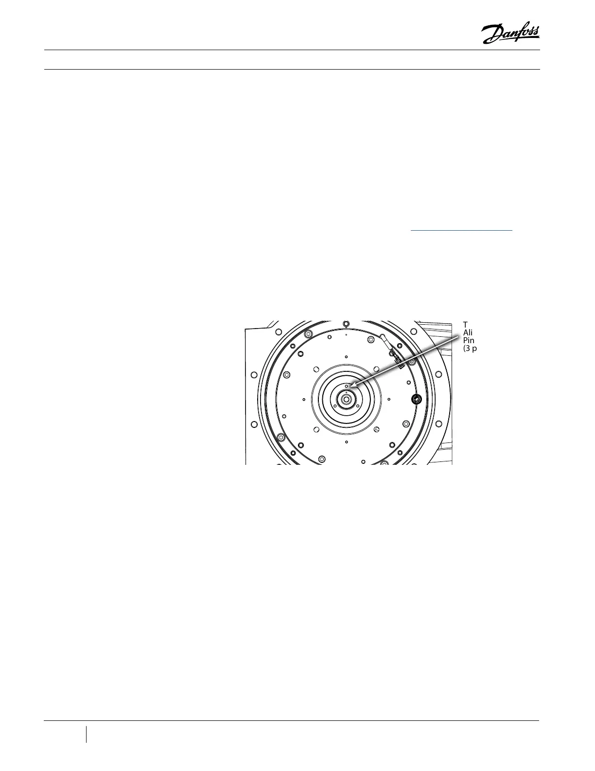
5. Insert at least two (2) Thrust Disk Alignment Pins (refer to the “Thrust Disk Alignment Pin”
example in Appendix B) into the threaded holes in the Compressor shaft. Refer to Figure
166 (Thrust Disk Alignment Pins) for the pin location. These pins are necessary due to the
magnetized shaft.
6. Carefully slide the Thrust Disk into place over the Compressor shaft and align it with the
inserted pins.
7. Remove all of the Thrust Disk Alignment Pins.
Figure 166 - Thrust Disk
Alignment Pins
Thrust Disk
Alignment
Pin Locations
(3 places)
8. Insert the three (3) M5x35 screws that secure the Thrust Disk and torque to specification.
9. Carefully slide the Axial Bearing Assembly into place over the Compressor shaft.
10. Install the four (4) M8x40 screws that secure the Axial Bearing Assembly and tighten them in a
crisscross pattern in two (2) stages.
• Stage 1: Tighten to 15 Nm (11 ft.lb.)
• Stage 2: Tighten to a final torque of 30 Nm (22 ft.lb.)
11. Verify all feed through contact surfaces are clean and dry. If not, clean with a lint-free cloth.
12. Apply Super-O-Lube to the new O-rings and then fit them into the O-ring grooves.
13. Orient the feed throughs with the notch at the top as shown in Figure 167 (Rear Bearing Sensor
Feed Through) and Figure 168 (Rear Bearing Power Feed Through).

 Loading...


