147 of 165
M-SV-VT-001-EN Rev. A
OEM Module Components
J24 Fan Connector
5.1.2.1 Fan Removal and
Installation
Removal:
1. Isolate the Compressor power as described in the “Electrical Isolation of the Compressor/VFD”
section of this manual.
2. Remove the four (4) M4x35 socket head cap screws with a 3 mm hex bit.
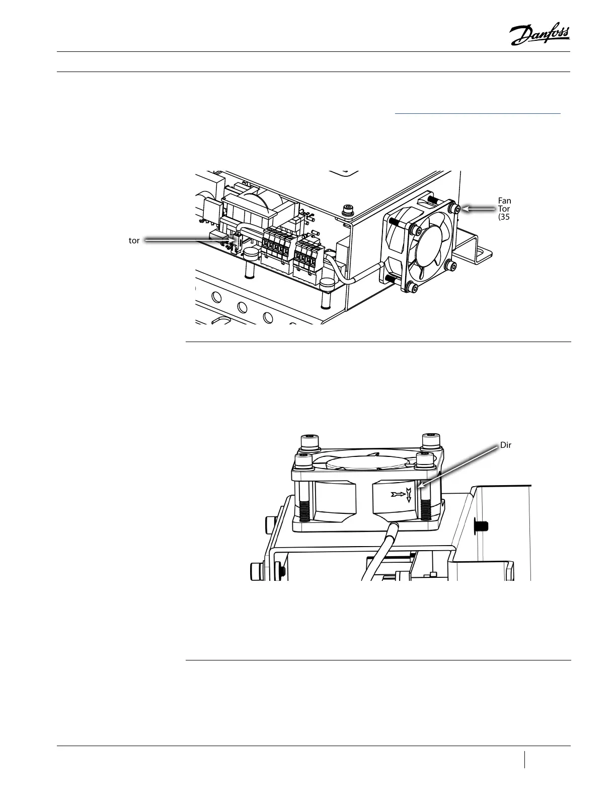
3. Remove the fan connector from J24 on the DC-DC Board. Refer to Figure 190 (Fan Connector).
Figure 190 - Fan Connector
Fan Screws,
Torque to 4 Nm
(35 in.lb.) (4 places)
Installation:
1. Assemble the four (4) new M4x35 screws along with the four (4) new flat and split washers.
2. Mount the fan to the DC-DC in the proper direction. There is an arrow on the fan housing that
should be pointing towards the DC-DC. Refer to Figure 191 (Fan Orientation).
3. Using a 3 mm hex bit, attach the new fan to the DC-DC with the new four (4) M4x35 screws and
Figure 191 - DC-DC Fan
Orientation
Direction of Airow
torque to specification.
4. Install the connector for the new fan to J24 on the DC-DC Board.
5. Reconnect power to the compressor.
Verication (Revisions A and B):
1. Ensure all connections are correctly installed.
2. Apply power to the VTT VFD.
3. Verify the LEDs on the CIM are illuminated.
5.1.3 DC-DC Verication

 Loading...


