58 of 165 M-SV-VT-001-EN Rev. A
Compressor Components
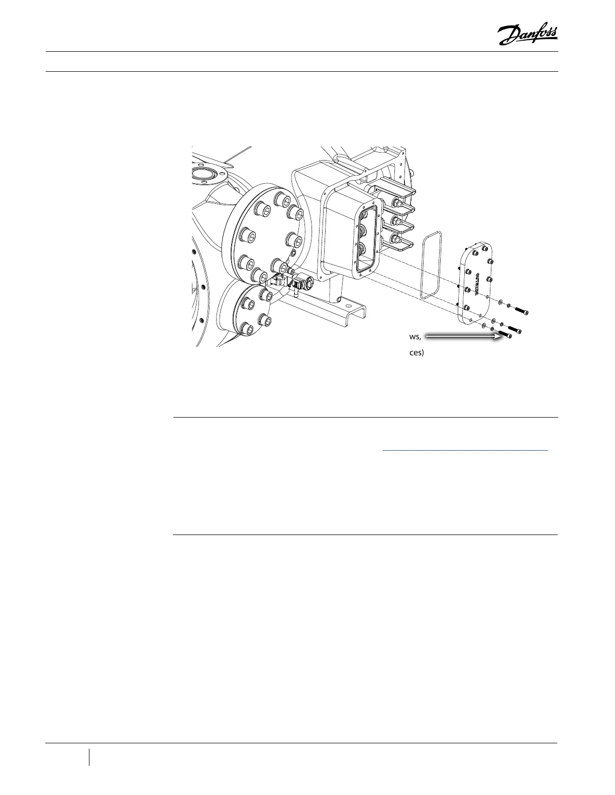
3.3.4 Tower Plate
The Tower Plate covers access to the motor power connection of the internal motor cables while
preventing refrigerant pressure from escaping.
Figure 52 - Tower Plate
3.3.4.1 Removal and
Installation
Tower Plate Removal:
1. Isolate the Compressor power as described in the “Electrical Isolation of the Compressor/VFD”
section of this manual.
2. Isolate the Compressor and recover refrigerant.
3. Remove the Motor Power Cover.
4. Remove the screws from the Tower Plate.
5. Remove the plate and O-ring.
Tower Plate Installation:
1. Verify all sealing and internal surfaces are clean and dry. If not, clean with a lint-free cloth.
2. Clean the O-ring groove.
3. Ensure no parts, tools, or debris are left in the Motor Tower.
4. Apply Super-O-Lube to the new O-ring and then fit it into the O-ring groove on the Compressor
tower.
5. Place the Tower Plate over Motor Tower with the writing “OUTSIDE” facing away from the tower.
6. Finger-tighten the 10 M6 screws.
7. Tighten the 10 M6 screws in a crisscross pattern in two (2) stages. Refer to Figure 53 (Tower Plate
Torque Pattern).
• Stage 1: Tighten to 5 Nm (44 in.lb.)
• Stage 2: Tighten to a final torque of 10 Nm (88 in.lb.)
Tower Plate Screws,
Torque to 10 Nm
(89 in.lb.) (10 places)

 Loading...


