25 of 165
M-SV-VT-001-EN Rev. A
4
12
1
7
8
9
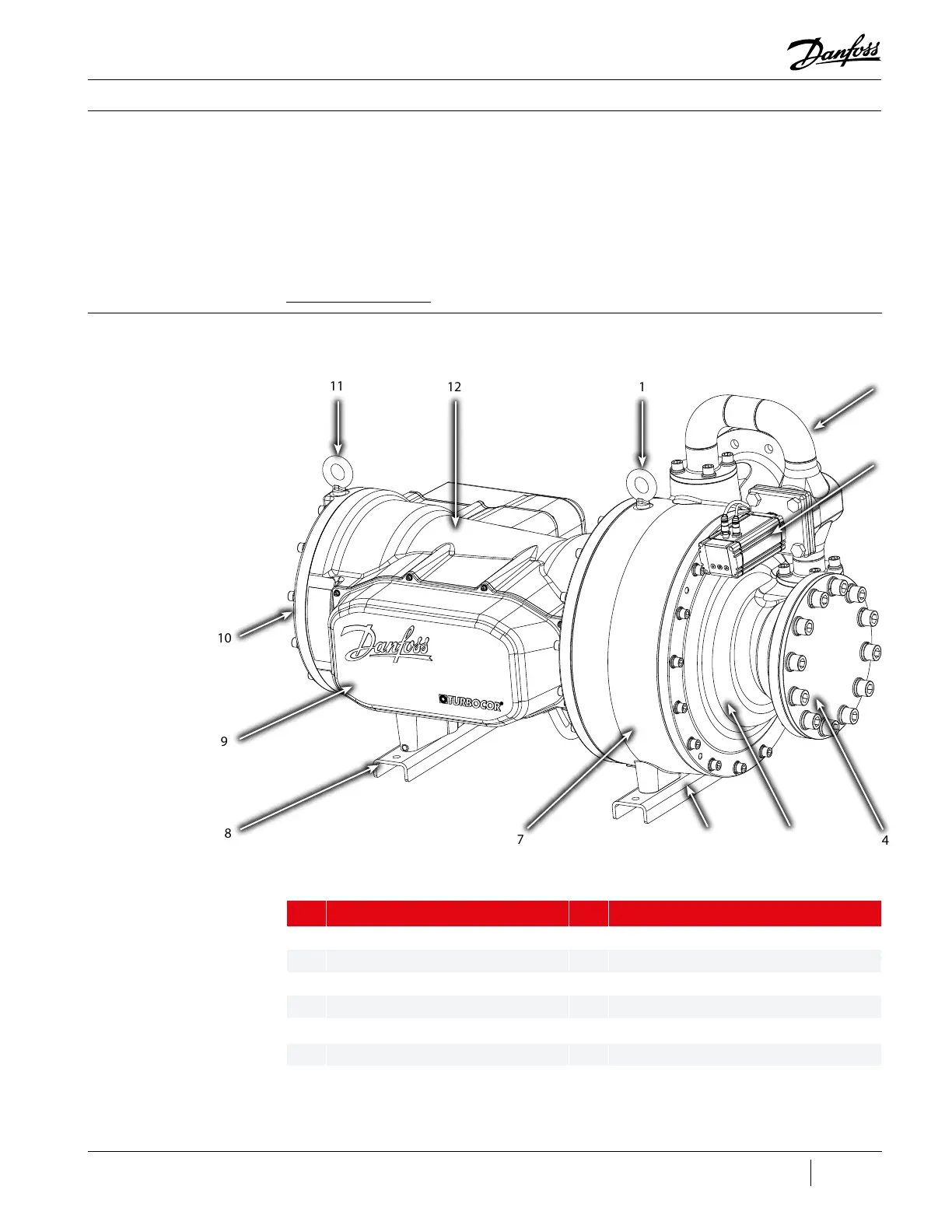
Compressor Components
Table 1 - Compressor
Component Identication
(Service Side)
This section provides Compressor component locations and functional descriptions, verication
and troubleshooting methods, cable connection identication, and steps necessary to replace a
component.
At the time of this publication, there have been three (3) major revisions of the VTT Compressor.
Throughout this section, the various component dierences are identied if applicable. The most
recent revision of this Compressor, Major Revision “C,” allows for the use of some customer-supplied
cabling for the electronics. For details on the required cable type and maximum length, refer to the
VTT Applications Manual.
3.1 Component
Identication
This section identies the major parts of the Compressor.
No. Component No. Component
1 Lift Anchor (Front) 7 Volute (Second Stage Fluid Assembly)
2 IFV Pipe Assembly 8 Rear Support Base
3 IFV Actuator ICAD 1200A 9 Service Side Cover
4 Suction Flange 10 End Cap
5 Suction Housing 11 Lift Anchor (Rear)
6 Front Support Base 12 Motor Housing
5
6
2
3
11
10
Figure 11 - Compressor
External Component
Identication – Service Side

 Loading...


