53 of 165
M-SV-VT-001-EN Rev. A
Compressor Components
3.3.1.1 Removal and
Installation
Motor Power Cover Removal:
1. Isolate the Compressor power as described in the “Electrical Isolation of the Compressor/VFD”
section of this manual.
2. Remove the four (4) or six (6) screws that hold the Motor Power Cover in place.
3. Remove the Motor Power Cover.
Motor Power Cover Installation:
1. Verify all sealing surfaces are clean and dry. If not, clean with a lint-free cloth.
2. Install the gasket on the sealing surface of the cover.
3. Place the cover over the motor power side.
4. Install the screws to secure the Motor Power Cover and torque to specification.
5. Restore power to the Compressor.
3.3.1.2 Torque
Specications
Description Nm Ft.Lb. In.Lb.
Power Cover, SHCS, M5x16 6 - 53
Table 14 - Motor
Power Cover Torque
Specications
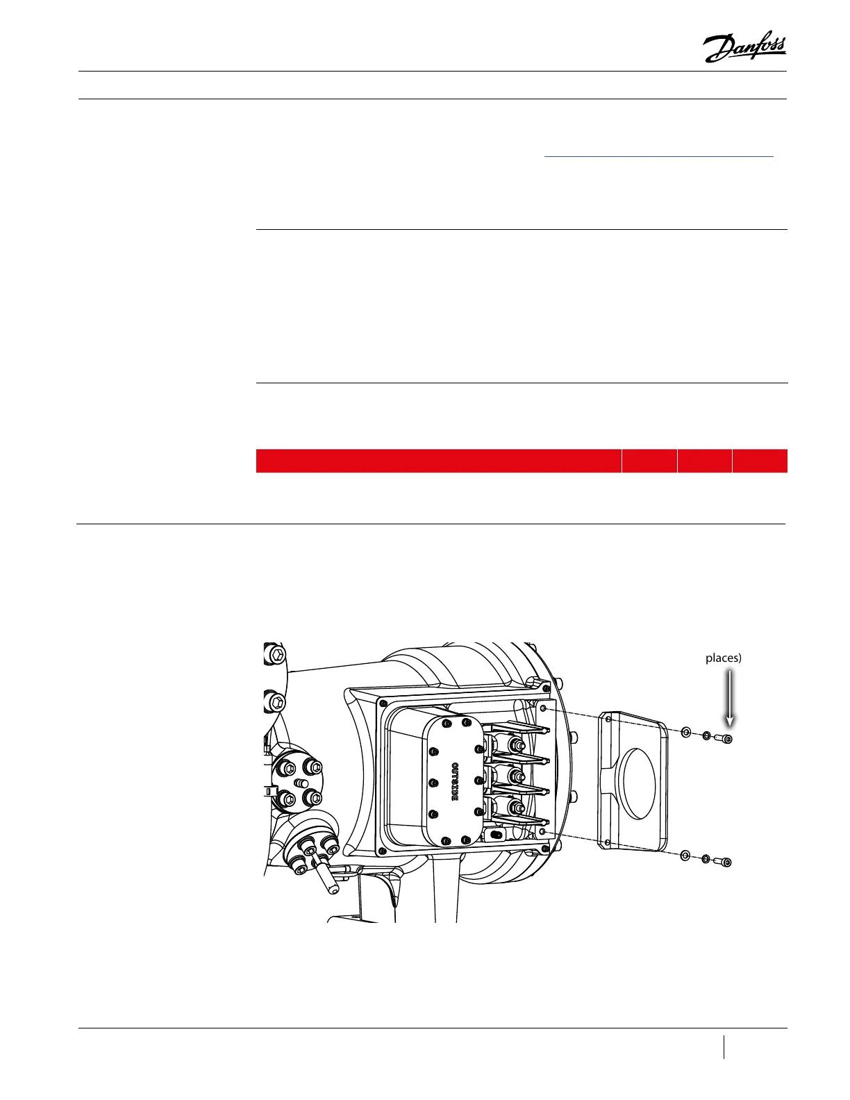
3.3.2 Mains Input Bracket The Mains Input Bracket provides support for the conduit of the cables from the VFD to the
compressor motor. There are two (2) variants of this bracket with the Revision A utilizing two (2)
mounting holes where as the Revisions C and later, utilize four (4) mounting holes.
Figure 48 - Mains Input
Bracket (Revision A)
Torque to 10
Nm (7 ft.lb.)
(2 places)

 Loading...


