48 of 165 M-SV-VT-001-EN Rev. A
Compressor Components
EXV Cable Installation:
1. Attach the Valve Actuator to the EXV.
2. Route the cable into the service side.
3. Connect the cable to the J15 EEV_MOT terminal on the CCM.
4. Secure the cable in the retaining clip.
5. Reinstall the Service Side Cover.
6. Restore power to the Compressor.
3.2.8.2 Verication
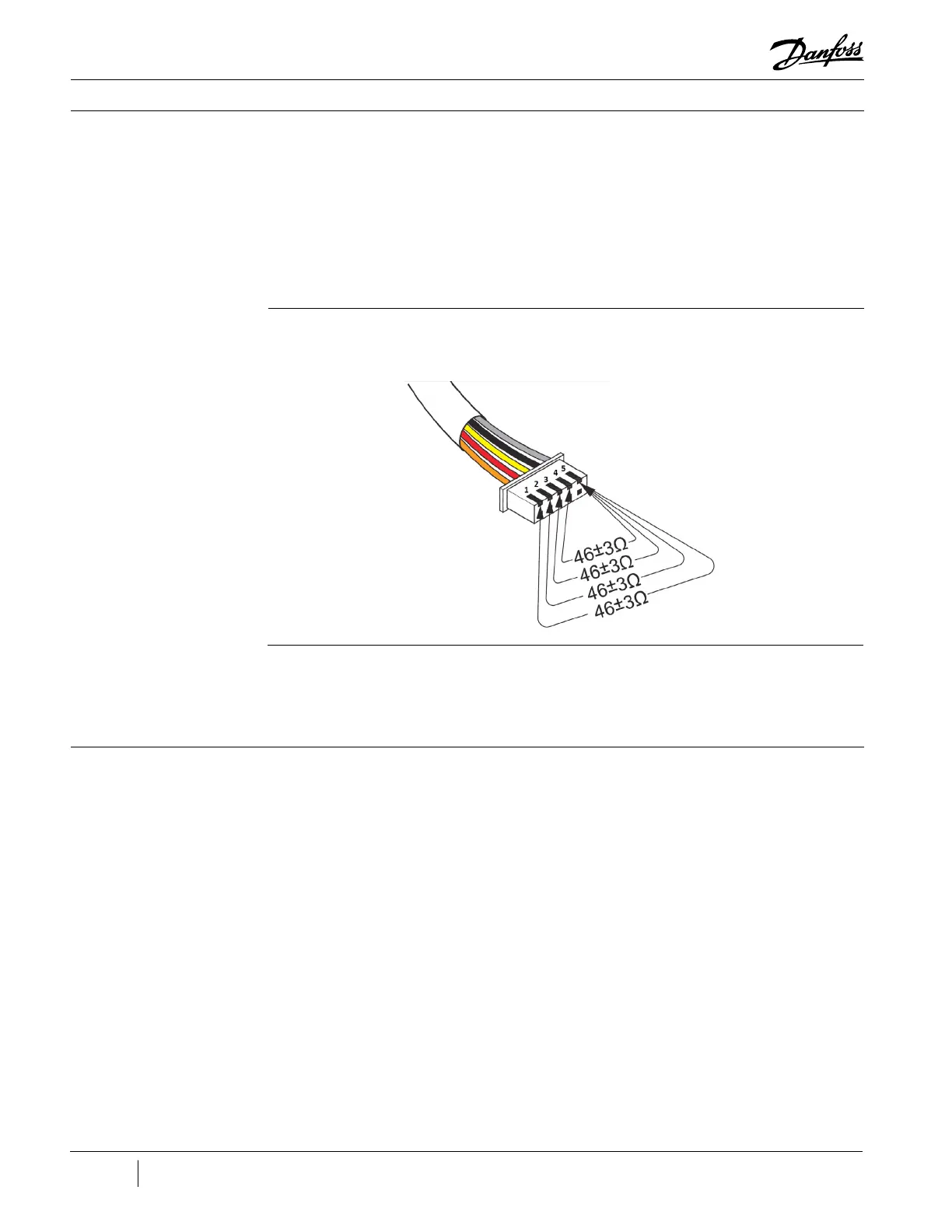
1. The Motor Cooling Valve Cable continuity and Actuator coil resistance can be measured by
checking the resistance from the Gray #5 wire to each of the four (4) other wires.
3.2.8.3 Running Check
Figure 42 - Cable Pinout
for Continuity/Resistance
Verication
1. The valve resets to 0% when power is first applied to the Compressor.
2. The valve opens to 15% for two (2) minutes at Compressor startup.
3. While running, it is controlled based on superheat temperature as refrigerant exits the motor.
3.2.9 Motor Cooling
Exit Flange
The motor cooling ow exits the Compressor in the Motor Cooling Exit Flange.
There are two (2) variants of the Motor Cooling Exit Flange, both perform the same function but are
not interchangeable due to the mounting ange design. The O-ring is identical between the two (2)
variants.

 Loading...


