79 of 165
M-SV-VT-001-EN Rev. A
Compressor Components
Figure 80 - DC-DC-CCM
Cable (Revisions C and
Later)
3.7.1.4.1 Removal and
Installation
Removal (Revisions A and B):
1. Isolate the Compressor and VFD power as described in the “Electrical Isolation of the
Compressor/VFD” section of this manual.
2. Remove the Service Side Cover.
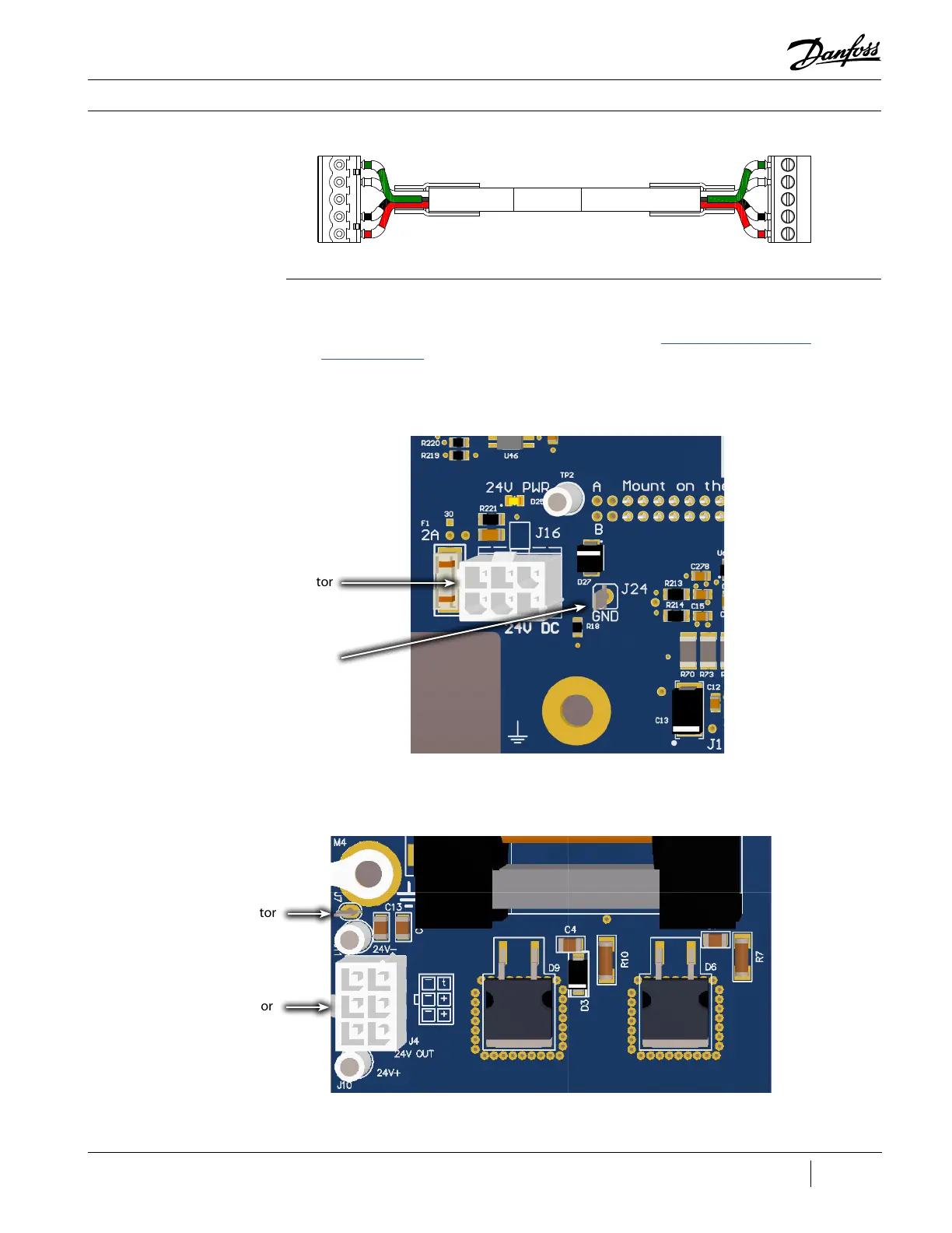
3. Disconnect the 24 VDC (J16) and GND (J24) connectors from the CCM Board.
Figure 81 - J16 and J24
(Revisions A and B)
J16 Connector
J24 Connector
4. Remove 24 VDC (J4) and GND (J7) from DC-DC Board.
Figure 82 - J4 and J 7
(Revisions A and B)
J7 Connector
J4 Connector
5. Remove the cable between the CCM and DC-DC.

 Loading...


