149 of 165
M-SV-VT-001-EN Rev. A
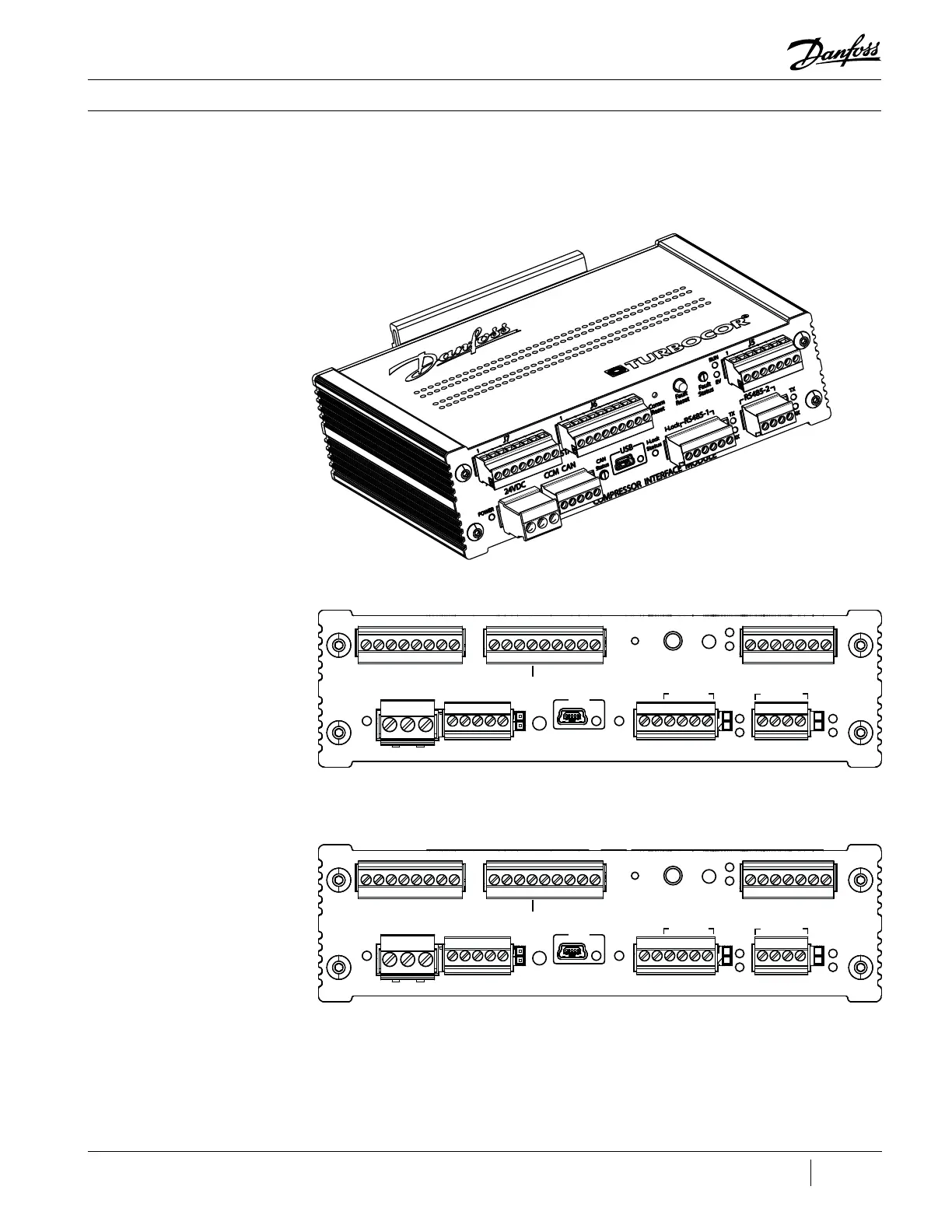
OEM Module Components
6.1 Compressor Interface
Module (CIM)
The CIM is where all eld connections, such as RS485, EXV and analog/digital wiring, is made to
communicate with the compressor. As previously stated, there are two (2) variants of the CIM.
Revisions A and B do not contain the connector numbers on the front plate (e.g., J5). The “Pin 1”
indicators are also not present on the A and B revisions.
Figure 194 - CIM (Revision C
Shown)
Figure 195 - CIM Faceplate
(Revisions A and B)
Figure 196 - CIM Faceplate
(Revisions C and Later)
Comm
Reset
Fault
Reset
Fault
Status
EV
TX
STATUS
RUN
TX
RX
RX
RS485-1
I-Lock
STAGING VFD COOLING
CAN
Status
24VDC
AUX P/T SENSORS
COMPRESSOR INTERFACE MODULE
POWER
CCM CAN
USB
I-Lock
Status
RS485-2
Comm
Reset
Fault
Reset
Fault
Status
EV
TX
STATUS
RUN
TX
RX
RX
RS485-1
I-Lock
STAGING VFD COOLING
CAN
Status
24VDC
AUX P/T SENSORS
COMPRESSOR INTERFACE MODULE
POWER
CCM CAN
USB
I-Lock
Status
RS485-2
J7
1
1
1 1 1
1
1
J6 J5
J4J3J2
J1

 Loading...


