EasyManuals Logo
Home>Danfoss>Air Compressor>Turbocor VTT Series

Danfoss Turbocor VTT Series User Manual

Danfoss Turbocor VTT Series
165 pages
To Next Page IconTo Next Page
To Previous Page IconTo Previous Page
Page #124 background imageLoading...
Page #124 background image
124 of 165 M-SV-VT-001-EN Rev. A
Compressor Components
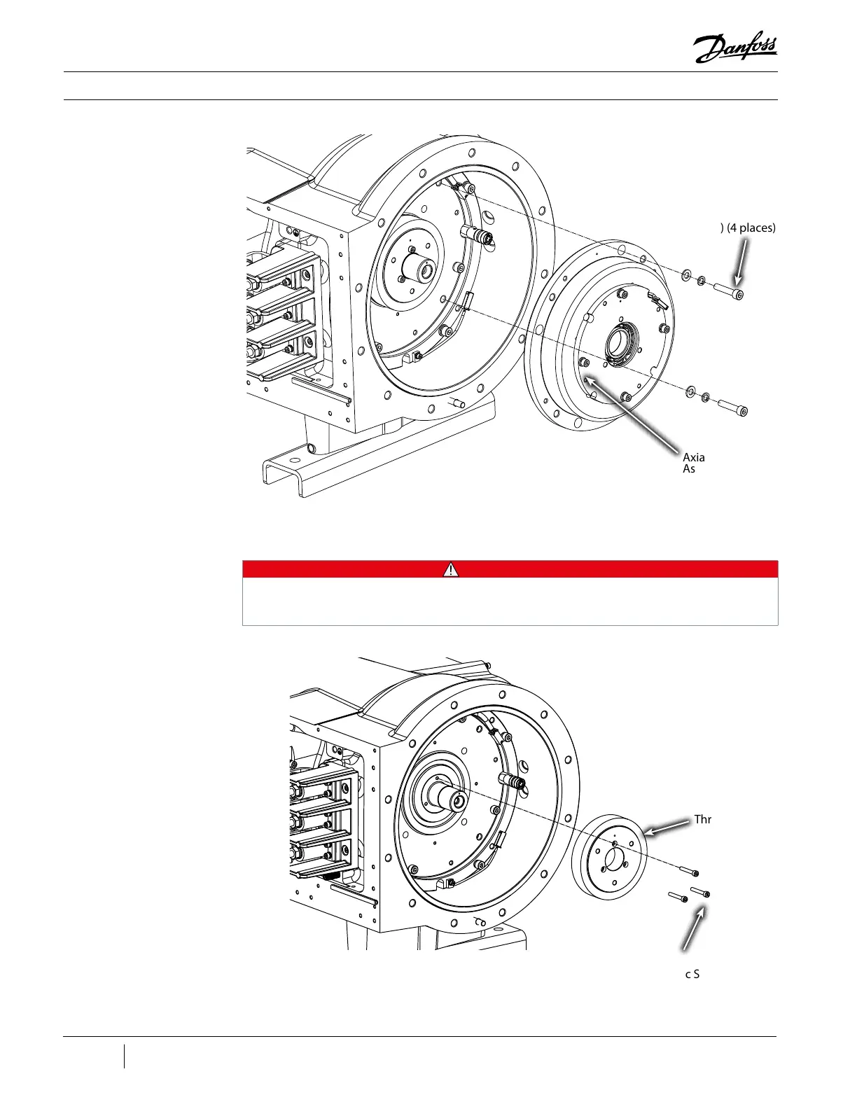
Figure 158 - Axial Bearing
Removal
Axial Bearing
Assembly
Thrust Disk
Figure 159 - Thrust Disk
Removal
12. Remove the three (3) M5x35 screws that secure the Thrust Disk and carefully slide the Thrust
Disk off the Compressor shaft.
• • • CAUTION • • •
All magnetic parts MUST be separated and placed in individual bags that can be sealed to
prevent contamination to the parts. Metal debris can and will lead to premature failure of the
Compressor components.
Axial Bearing
Screws - 30 Nm (22
ft.lb.) (4 places)
Thrust Disc Screws
- 10 Nm (89 in.lb.)
(3 places)

Table of Contents

Questions and Answers:

Question and Answer IconNeed help?

Do you have a question about the Danfoss Turbocor VTT Series and is the answer not in the manual?

Danfoss Turbocor VTT Series Specifications

General IconGeneral
BrandDanfoss
ModelTurbocor VTT Series
CategoryAir Compressor
LanguageEnglish

Related product manuals