85 of 165
M-SV-VT-001-EN Rev. A
Compressor Components
Installation:
1. Attach wires to terminals 61, 68, 69, 12, and 19.
2. Route Cable into service side box.
3. Connect plug to (J4) on CCM.
4. Replace the covers.
5. Restore power to the Compressor.
1. With Power applied to the Compressor, connect to the CIM using the SMT and enter the User ID
and Access Code.
2. Open the Warnings and Faults Tool.
3. Verify that the CIM Compatibility, CAN Communications and VFD Communications Faults are
not active.
3.7.1.6.2 CCM-VFD Cable
Verication
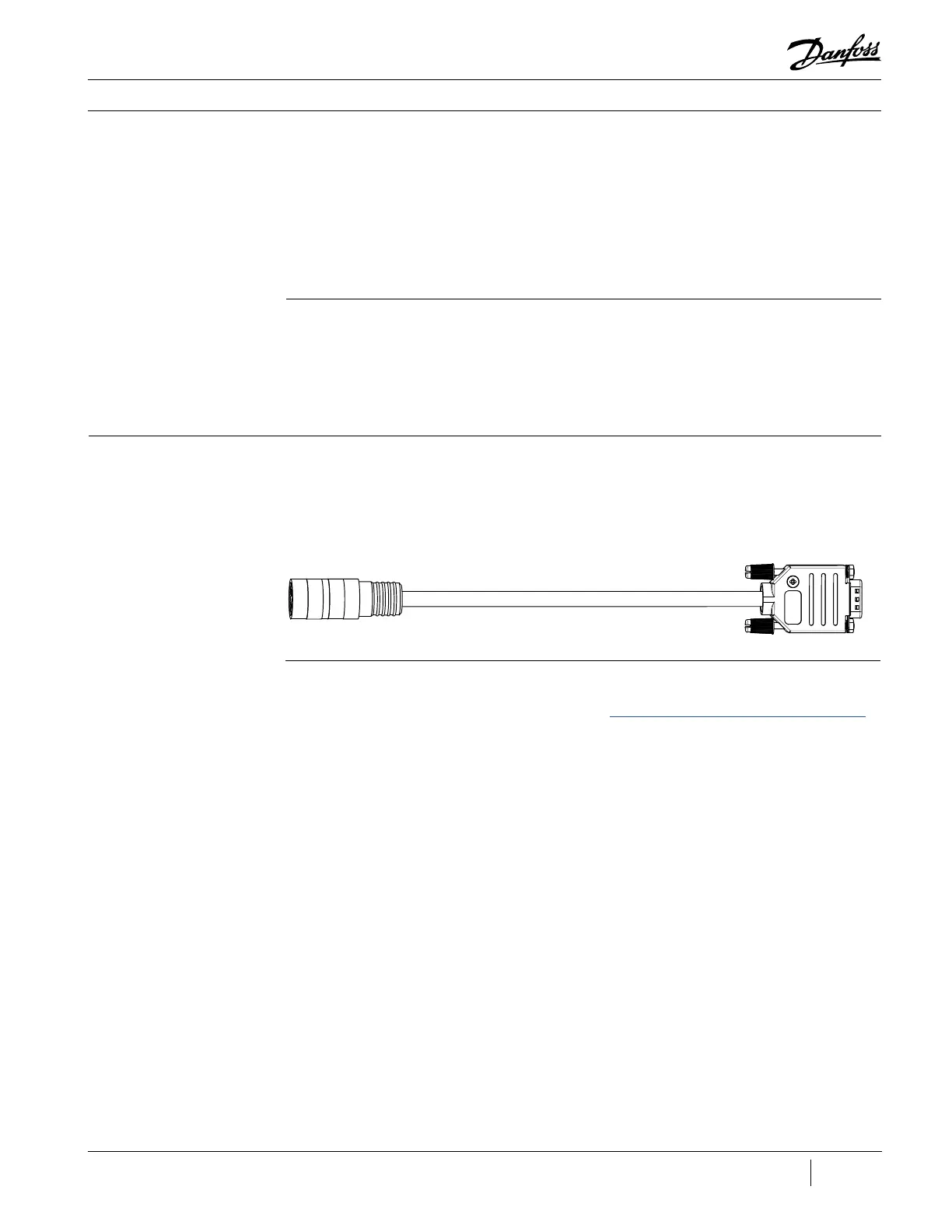
3.7.1.7 Front Bearing
Sensor Cable
Figure 95 - Front Bearing
Sensor Cable
3.7.1.7.1 Removal and
Installation
Removal:
1. Isolate the Compressor power as described in the “Electrical Isolation of the Compressor/VFD”
section of this manual.
2. Remove the Service Side Cover.
3. Remove the 9-pin connector from J6 on the CCM Board.
4. Twist and pull to remove the sensor cable connection from the feed through.
The Front Bearing Sensor Cable provides shaft position information from the Front Bearing Sensor
Feed Through to the CCM.

 Loading...


