65 of 165
M-SV-VT-001-EN Rev. A
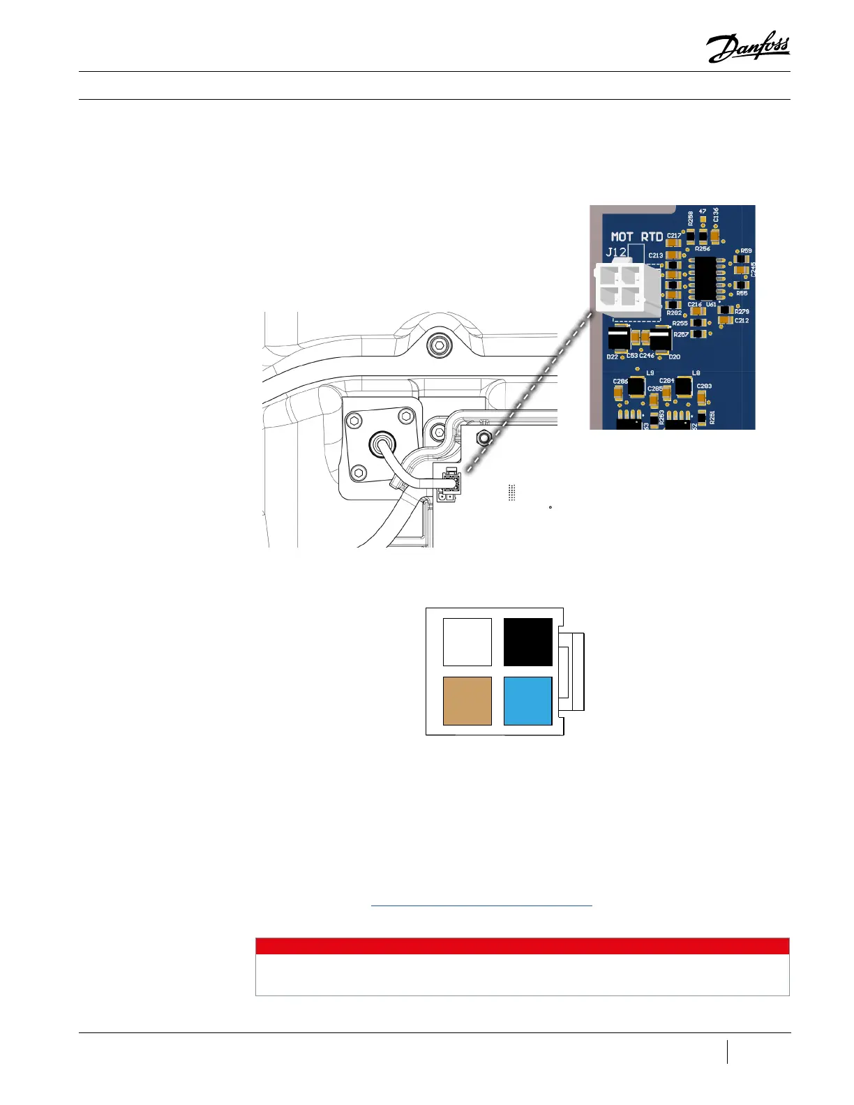
Figure 60 - Stator
Temperature Sensor Cable
External Connector
NOTE
Both are approximately 1.09kΩ at 22°C (72°F). Refer to Table 20 (Stator Thermistor R/T Curve) for
further values.
2 4
1 3
3. Unplug the winding temperature harness from the J12 connector on the CCM.
4. Verify the resistance of each circuit at the external connector to CCM J12.
5. Circuit one, pins 1 and 3, are brown and blue.
6. Circuit two, pins 2 and 4, are white and black.
7. Using a multimeter set for resistance measurements, place the red (+) multimeter lead on
pin 1 and the black (-) multimeter lead on pin 3 of the external connector and record the
measurement.
8. Perform the same resistance measurement for pins 2 and 4 of the external connector. If the
measured value does not correspond to the expected resistance, then the internal connector
must be checked in order to verify if the problem exists in the feed through or the Stator itself.
Refer to section “Stator Temperature Sensor Feed Through” for details regarding accessing the
internal connector.
Figure 59 - Stator Temperature
Sensor Cable Connector
Compressor Components

 Loading...


