73 of 165
M-SV-VT-001-EN Rev. A
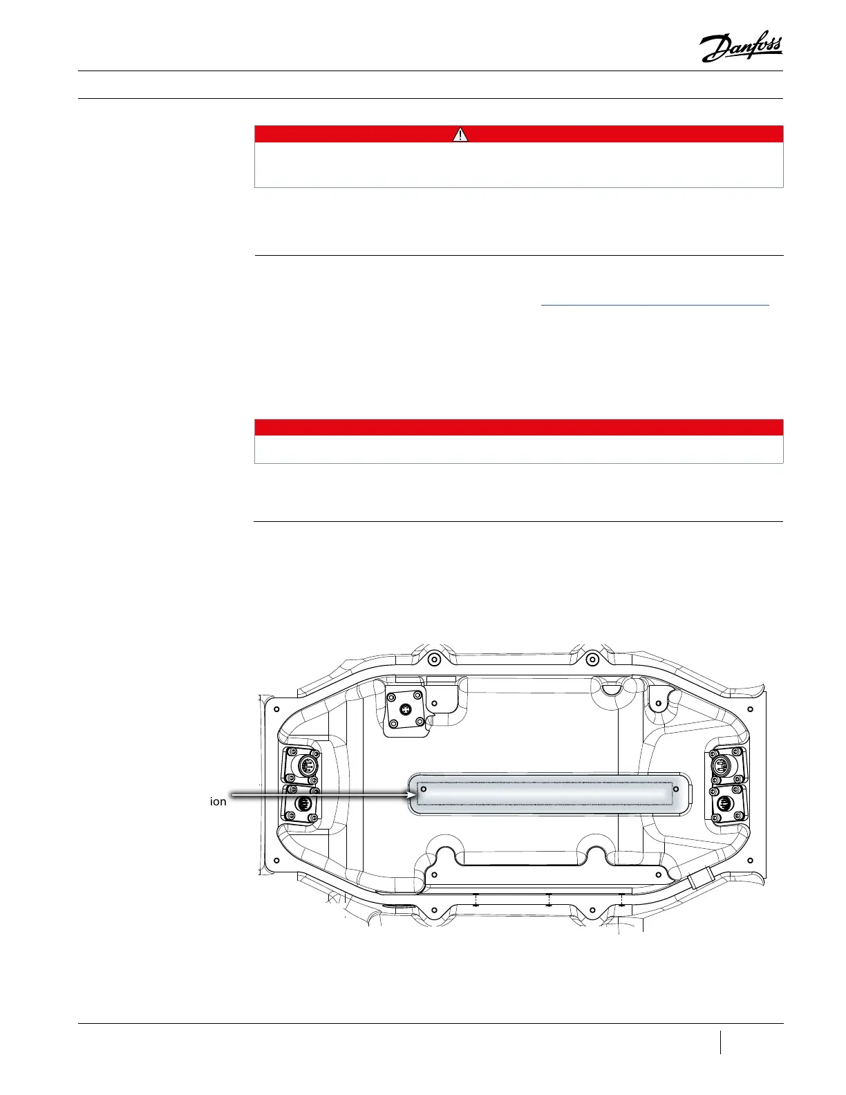
Thermal Paste
Application Location
• • • CAUTION • • •
Follow established ESD procedures to prevent damage to sensitive electronic components when
working on the Service Electronics Assembly.
3.7.1.1 Removal and
Installation
The CCM and PWM Boards cannot be serviced separately, therefore the Service Electronics Assembly
will need to be replaced should there be a fault with either the CCM or the PWM.
Removal:
1. Isolate the Compressor power as described in the “Electrical Isolation of the Compressor/VFD”
section of this manual.
2. Remove the Service Side Cover.
3. Disconnect the power and communications cables from the CCM and PWM.
4. Disconnect all cables going to the VTT Service Electronics Assembly.
5. Remove the PWM heat sink fasteners and ground wires (if applicable).
NOTE
The various connections are illustrated throughout this section.
6. Remove the fasteners that secure the Service Electronics Assembly plastic frame to the main
housing and then remove the Service Electronics Assembly.
Installation:
1. Clean the Compressor housing and apply a thin layer of thermal paste to the PWM heat sink
surface of the main housing. Refer to Figure 70 (Thermal Paste Application).
Figure 70 - Thermal
Paste Application

 Loading...


