57 of 165
M-SV-VT-001-EN Rev. A
Compressor Components
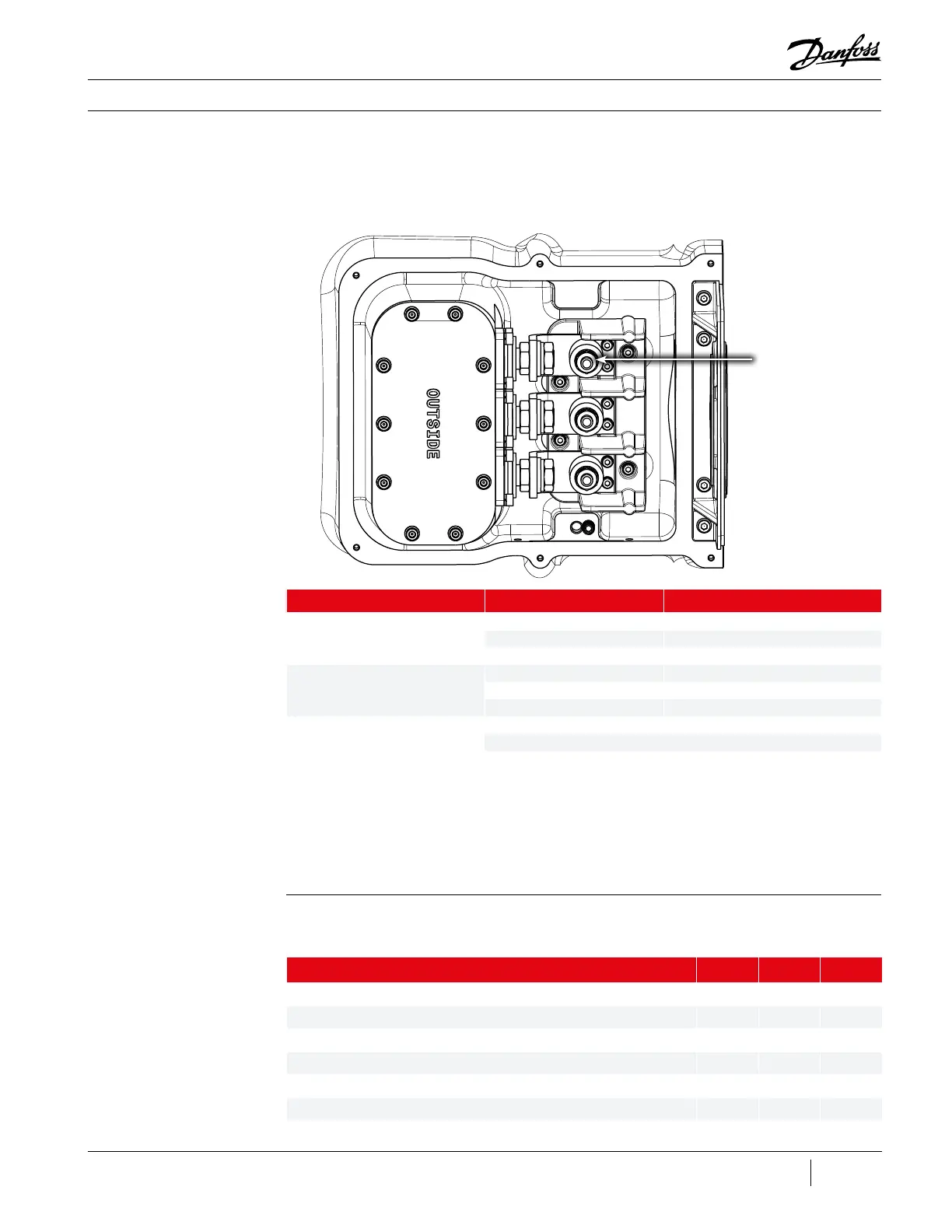
3. Place the meter probe on one phase of the AC input posts and the other meter probe on
another phase of the AC input as shown in Figure 51 (Measuring AC Input Voltage).
4. Verify that the meter shows the expected AC measurement within the range as indicated in
Table 16 (Expected AC Voltage Range).
Figure 51 - Measuring AC
Input Voltage
Description Nm Ft.Lb. In.Lb.
Power Cover, SHCS, M5x16 6 5 53
Motor Terminal Block to Compressor, SHCS, M5x20 6 5 53
Tower Feed Through Nut, Brass M16x1.5 20 15 177
Power Cable Nut, Brass M10x1.5 10 8 89
Bus Bar Mounting, SHCS, M5x16 5 4 44
Ground Cable Nut, M10x1.5, Brass 20 15 177
Table 17 - Motor
Terminal Block Torque
Specications
Table 16 - Expected AC
Voltage Range
3.3.3.3 Torque
Specications
5. If the meter does not show any reading, it is possible that there is no power from the VFD.
Measure again but this time verify the 3-phase output at the VFD.
6. If the meter still does not show any reading, ensure the AC power source is turned ON and try again.
7. If the measured values correspond to the specified values for all phases, the AC input voltage is okay.
AC Input Posts
(3 places)
VFD Module Nominal Voltage Acceptable Voltage Range
N165 T5
380 342-418
400 360-440
460 414-506
N232 T5
380 342-418
400 360-440
460 414-506
N262 T5
380 342-418
400 360-440
460 414-506

 Loading...


