78 of 165 M-SV-VT-001-EN Rev. A
Compressor Components
4. Remove the cover to the controls panel where the CIM is located.
5. Remove the 24 VDC connector from the CIM.
6. Route the cable out of the service side and CIM boxes.
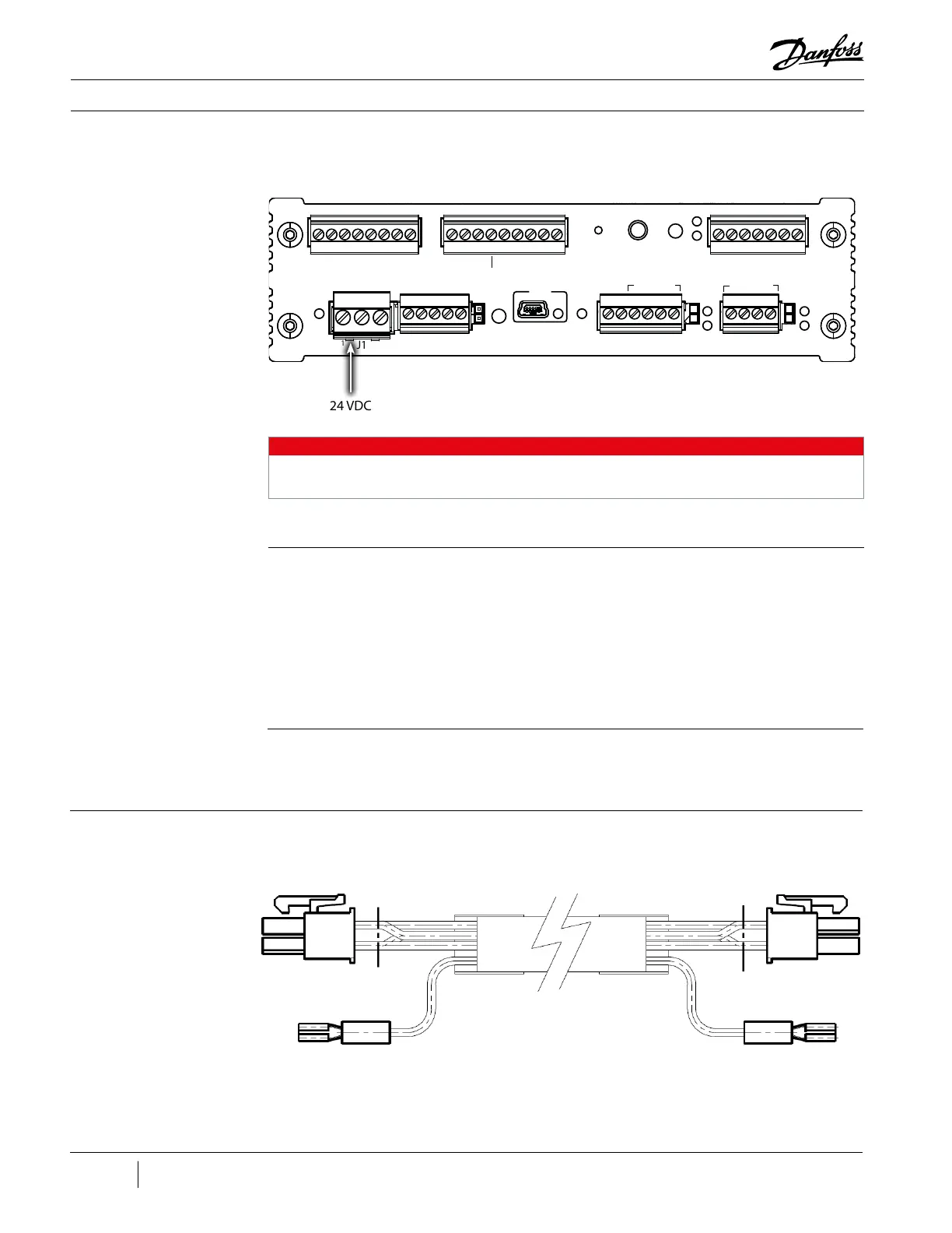
Figure 78 - 24 VDC
Connector at CIM
Comm
Reset
Fault
Reset
Fault
Status
EV
TX
STATUS
RUN
TX
RX
RX
RS485-1
I-Lock
STAGING VFD COOLING
CAN
Status
24VDC
AUX P/T SENSORS
COMPRESSOR INTERFACE MODULE
POWER
CCM CAN
USB
I-Lock
Status
RS485-2
J7
1
1
1 1 1
1
1
J6 J5
J4J3J2
J1
24 VDC
Connector
NOTE
There are two (2) variants of the CIM. Revisions A and B do not contain the connector numbers
(e.g., J5). The “Pin 1” indicators are also not present on the A and B revisions.
Installation:
1. Route the new cable between the CCM and CIM.
2. Insert the 24 VDC connector to the CIM.
3. Insert the 24 VDC connector into J7 on the CCM Board.
4. Replace the covers.
5. Restore power to the Compressor.
3.7.1.3.2 24 VDC CCM-CIM
Cable Verication
After power is applied to the Compressor, ensure the light emitting diodes (LEDs) on the CIM are on
and communication is established.
3.7.1.4 DC-DC-CCM
24V Cable
The DC-DC-CCM 24V Cable passes 24 VDC from the DC-DC to the CCM.
Figure 79 - DC-DC-CCM
Cable (Revisions A and
B)

 Loading...


